This dialog controls settings that can affect the appearance of your results. All settings are stored in the system Registry at:
Computer\HKEY_CURRENT_USER\Software\VB and VBA Program Settings\XL2DWG\General
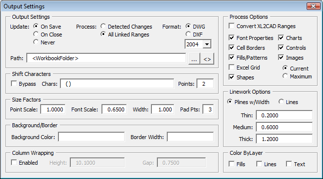
The sections of the dialog are explained below.
Output Settings:
- Update: You can designate when the application should update linked files. If you have large spreadsheets and save often, you may consider changing to On Close. If you have CAD projects waiting for up to the minute changes use the default On Save option.
- Process: Designates the time when the application will automatically update any DWG/DXF files that have changed in the current editing session. The On Close option can take less time as it only updates once (when the spreadsheet closes). However some users may want the output to update on each save.
- Format: The application can save the drawing in a DWG or DXF format. Choose the desired output and optionally specify the file version to create. Note that 2004 was the first format to support true color so choosing 2000 format will reduce the colors to AutoCAD's original 256 colors.
- Path: This is the folder where the DWG/DXF files are written to.
By default the files are placed in the path where the spreadsheet is located, using the special value
<WorkbookFolder>in the path field.Note: The use of
<WorkbookFolder>when opening Cloud-based documents may throw Run-time error '52'.You can append sub-folder names to the key, such as <WorkbookFolder>\DWG in this case the file will be stored in the DWG subfolder. If the subfolder level is one level deep (such as this example), the application will create the subfolder for you. If nested subfolders are used, like <WorkbookFolder>\SubFolder\DWG, the folders must be created ahead of time yourself. If you use nested subfolders and the folders do not pre-exist, the application will use the workbook folder instead.
You can also enter a specific drive\path to place the DWG/DXF files or use the button to select one.
Shift Characters:
Certain characters can cause the text objects to appear to shift (usually down). Typical characters include parenthesis, ascenders, descenders, etc.
- Bypass: Turn on this toggle to bypass the shift system. No adjustments will be made to the insertion position. This lets you keep your settings such as characters and bypass the system on an as-needed basis.
- Chars: Enter the shift characters you wish to check and compensate for.
- Points: This is the number of points to shift the text object vertically. To get a feel for the unit, keep in mind the typical piece text is 10 points high.
Size Factors:
Certain characters can cause the text objects to appear to shift (usually down). Typical characters include parenthesis, ascenders, descenders, etc.
- Point Scale: See the section on scale in the Placing the Table section above.
- Font Scale: This is the size percentage of the font to the designated size. For example, in a 10pt font most characters are not 10pts high. Only the tallest characters such as "[" come close to this size. As such, a 10pt font could not be 10 units in AutoCAD, or it would overflow the cell. The default value of 0.65 closely simulated the relationship found in applications like Excel.
- Pad Points: This is the amount of padding inside the cell, the value in points.
Background/Border:
These options allow you to place an optional background solid in the table, and an optional border around the table. The background solid is drawn first so it's always in back of all the table geometry, the border is always drawn last so it's on top of all geometry.
- Background Color: Enter an ACI color number 1-255. Leave this field blank to skip the background.
- Border Width: Enter an absolute width for the border. This width is not scaled by the scale factor. Leave this field blank to skip the border.
Column Wrapping:
This option allows you to specify the maximum distance to travel down before moving back to the top to continue with an adjacent column.
- Enabled: Turn on this toggle to enable the system and use column wrapping. Adjacent options will become enabled.
- Height: The maximum vertical distance the text travels before it wraps. Pick or enter the distance in actual drawing units.
- Gap: This is the (space) distance between each column in a multi-column result, in actual drawing units.
Process Options:
- Convert XL2CAD: If this toggle is turned on, whenever a spreadsheet is opened the application will check for ranges created by our XL2CAD application. If they are found, the signature required by Excel2DWG is added so the ranges behave as if they were created by Excel2DWG. Note that the range name remains XL2CAD_20110811010203, etc.
- Font Properties: Turning off this toggle can improve speed somewhat as the application reads only the text string, not the justification, color, bolding, etc.
This option can also be used as a font override. In your CAD application set your text font/style properties and turn this toggle off. The resulting annotation will be generated in that current style.
- Cell Borders: If your spreadsheet has no borderlines, turn off this toggle.
- Fills & Patterns: If you don't have any color fills or patterns in your drawing, turning off this toggle can speed up the processing somewhat. Don't forget to turn it back on when you are preparing to process another spreadsheet that may contain them.
- Excel Grid: Controls whether the import will include grid lines from the spreadsheet. Users who make use of cell borders in Excel should leave this toggle off.
- Images: Controls whether the import will include Excel images. For speed and size consideration, the default resolution is the current scaled image in Excel. If your end results in the DWG file have grainy images, you can set the option to maximum. At maximum, if higher resolution data is available it will be used. However this usually results in larger image files and slows the processing slightly.
The availability of increased resolution depends on what was originally placed into Excel. This application cannot increase the resolution, only use the higher resolution data if it is available.
Linework Options:
Several options are available that can affect the appearance of the resulting linework.
- Object Type: By default the application draws linework as lwpolylines so that they can display width. You can override this and force the application to use line objects by switching to the Draw Line Objects radio button.
- Polyline Width Factors: If you use the default polyline linework option, you can change the scale factors assigned to the thin, medium, and thick polyline widths.
Color ByLayer:
These toggles allow you to override the object colors. By default the object is drawn with the hardcoded color to match the Excel color. If these toggles are turned on, the objects will instead be assigned a ByLayer color and placed on a layer with a name matching its object type and initial color. Turning these on allows more control by the parent document using layer colors.