Automated Hookup Procedure
When the application was installed (assuming your CAD engine was not running) it added hookup information to the supported versions. All you have to do is start your CAD application and the LegalWriter command will be defined. If you remove and reinstall your CAD application, or if you install a new version of your CAD application, the easiest way to restore this add-on is to double click the autohook.exe file in the applications folder. When this application is uninstalled it will automatically remove the hooks applied during installation as well as those added with the procedure below.
Manual Hookup Procedure
- Start your supported CAD application.
- Issue the NETLOAD command.
- Browse to the installed folder, the default is:
- 64-bit:
C:\Program Files\DotSoft\LegalWriter - 32-bit:
C:\Program Files (x86)\DotSoft\LegalWriter
- 64-bit:
- Choose the appropriate DLL for your CAD version from the table below:
LegalWriter DLL Files per CAD Application/Version Platform Version Module AutoCAD 2025 LegalWriterAC25.dll AutoCAD 2018-2024 LegalWriterAC18.dll AutoCAD 2015-2017 LegalWriterAC15.dll BricsCAD V24 Pro+ LegalWriterBC24.dll BricsCAD V23 Pro+ LegalWriterBC23.dll BricsCAD V22 Pro+ LegalWriterBC22.dll BricsCAD V21 Pro+ LegalWriterBC21.dll BricsCAD V20 Pro+ LegalWriterBC20.dll IntelliCAD 12.1 LegalWriterIC121.dll IntelliCAD 12.0 LegalWriterIC120.dll IntelliCAD 11.1 LegalWriterIC111.dll IntelliCAD 11.0 LegalWriterIC110.dll IntelliCAD 10.1 LegalWriterIC101.dll IntelliCAD 10.0 LegalWriterIC100.dll
AutoCAD Notes:
AutoCAD 2014+ Trusted Locations: Versions of AutoCAD since 2014 adds security which may require an additional procedure during manual setup.
- Launch AutoCAD.
- Issue the OPTIONS command.
- If you have multiple profiles, set your desired profile current.
- Click the [Profiles] tab.
- Select the profile from the list.
- Click the button.
- Click the [Files] tab.
- Click the to the left of Trusted Locations.
- Click the button.
- Click the button.
- Navigate to the application folder and click .
- If you receive an alert (about Read-Only), click .
- Click to close the Options dialog.
Folder: Because a single install of the application can serve both 32- and 64-bit environments, it installs (by default) to the Program Files (x86) folder.
IntelliCAD Notes:
- Due to variances of IntelliCAD builds (from different OEMs), we cannot currently automatically hook on. You will need to use the Manual Hookup procedure above.
- An IntelliCAD build might have the Microsoft .NET Framework support turned Off. In the event the NETLOAD command fails, issue the DOTNETENABLED command and enter ON. You will then need to close the CAD engine and restart it.
LegalWriter Usage
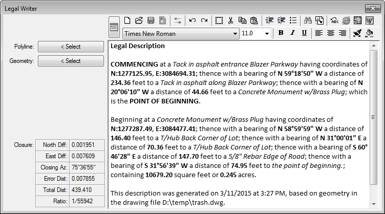
There are four sections of this dialog. They are the left pane (with closure results), editor and configuration windows (which overlay each other).
Left Pane:
This area is used when you want to process either a single polyline or a collection of lines and arcs. Once one of these buttons is chosen, and geometry is selected, the legal description will appear in the results frame to the right.
Alignment
Displays a list of the alignments (centerlines) defined in the current drawing/project. The writer can report station/offset values of the description corners with the [ALI*] fields. If alignments are present and the current defaults contain [ALI*] fields this tab will be set current on startup as a reminder to select an alignment.
- Distance Limit: If you don't want to include alignment references as points exceed a certain distance off the centerline, you can do so with a combination of two controls:
- First, in the template fields, enclose your alignment related calls in curly brackets, such as "to a [PntDesc]{ [AliOffset]' feet [AliSide] of station [AliStation] on [AliName]};".
- Second, specify the distance limit in the writer dialog. When a point is beyond this distance, all template content inside the curly brackets is discarded.
Polyline
This method is appropriate for a closed polyline boundary, and optional polyline commencement (reference) path. The Polyline origin and direction determines the path of the legal description. Once the dialog disappears, you will be prompted:
DS> Select Closed Polyline Boundary:

			DS> Select Reference Polyline (Enter to Bypass):
- Polyline Boundary: Select a single closed polyline representing the boundary.
- Reference Polyline: Optionally select a single open polyline representing the reference path. Often referred to as the commencement path. If a polyline is chosen, the program will list all the calls of this path before the main boundary.
The reference polyline can contain multiple segments, including arcs. The direction of the open polyline should flow towards and end exactly at the boundary beginning point.
Entities
This method is appropriate when using a collection of lines and arcs for the boundary and optional commencement path. Unlike a closed polyline, there is no logical starting point and direction, so you will be prompted for the origin and direction. Once the dialog disappears, you will be prompted:
			DS> Select Boundary Geometry:

			DS> Pick Origin Point of Legal Description:

			DS> Pick Second Point to Define Direction:

			DS> Select Reference Geometry (Enter to Bypass):
- Boundary Geometry: Select all line and arc segments that make up the boundary.
- Origin Point: Pick a point where the legal description of the boundary should begin. At this point, the program has turned off all osnaps except for endpoint, making it easier to pick the point.
- Second Point: Pick a point to show the direction you want the description to go. At this point, the program has turned off all osnaps except for endpoint and nearest. If this second point is on a line segment, you can pick anywhere along the line using the nearest osnap. However if the first segment is a curve, you must use the endpoint osnap to pick the other end of the curve!
- Reference Geometry: Select all line and arc segments that make up the reference path. This geometry should lead to the exact point of beginning of the boundary.
Parcels
- Parcel List: This list will display all the parcels defined in the current drawing or project. When using Vanilla CAD, parcels are stored internally as named groups.
- Process Button: Once the desired parcels are selected, this begins the process of generating boundaries. All the descriptions will appear together in the results window, each one separated by a horizontal line making it easy to determine when one starts and another begins.
- Select Multi: Turning on this toggle processes multiple parcels in the results.
- Off (Clear): In this mode you can only select one parcel at a time. As each parcel is selected its description is generated and displayed in the results window. The button is unused and grayed out.
- On (Checked): In this mode you can select multiple parcels using standard windows selection methods. This includes:
- Clicking on a single item, then holding the shift key to select another, with all items in between being selected.
- Holding the control key while clicking any item toggles between adding and removing it from those selected.
Once all desired parcels are selected, choose the button.
Results Editor:
This section contains the results display and editor, along with its control toolbar.
The display/editor serves a dual function. Its primary use is to display legal descriptions, but if necessary, it can also be used as a word processor to finalize a legal description. Be aware that because of the primary objective being to quickly display results, it does not bother prompting to save changes before its contents are replaced. Therefore, if you make changes in the editor you wish to retain, you should immediately save them to a file or print them.
The toolbar above the editor contains the following tools, first and second rows, from left to right.
First Row
- New: Immediately clears the contents of the editor.
- Open: Used to open an existing document file from disk.
- Save (Text): Saves the current contents of the editor to a file on disk.
- Save (Audio): Create a .WAV audio file comparable to reading the description aloud.
- Reverse: Immediately reverses the boundary description displayed in the editor.
- Print: Prints the current contents of the editor.
- Undo: Undoes the last change made to the contents.
- Redo: Undoes the last undo, restoring the contents to the state before the undo was made.
- Select All: Selects all the text in the editor.
- Cut: Cuts the selected text, placing it in the Windows clipboard.
- Copy: Copies the selected text, placing it in the Windows clipboard.
- Paste: Pastes the contents of the Windows clipboard at the current cursor position.
- Find: Finds a keyword in the document.
- Replace: Allows rapid find/replace operations in the document.
- Font: Changes the font properties of the selected text.
- Insert Text: Hides the dialog and prompts for you to select a text/mtext object in the drawing. The text contents of the object are placed into the description at the current cursor position.
- Send to Acad: Hides the dialog and prompts for placement parameters, then generates a mtext object in AutoCAD of the selected text. If no text is selected, it will automatically select all before beginning.
- Send to Word: Sends the selected text to Microsoft Word. If no text is selected, it will automatically select all before beginning.
- If an existing Word session is open, the selected text is inserted at the current cursor position.
- If Word is not open, a new session is launched, and the selected text is inserted.
If you don't use Microsoft Word, you can simply click the button, then the button, and you're ready to paste into any Windows compatible word processor.
Second Row
- Style List: Allows you to choose from previously established styles.
- Style Current: Used to set the displayed style as the loaded default.
- Font List: Allows you to choose any Windows font for the selected text.
- Font Size: Controls the font size of the selected text.
- Font Override: If depressed overrides font information in templates with values shown.
- Bold: Changes the bold status of the selected text.
- Italic: Changes the italic status of the selected text.
- Underline: Changes the underline status of the selected text.
- Alight Left: Aligns the selected text to the left.
- Center: Aligns the selected text to the center.
- Align Right: Aligns the selected text to the right.
- Numbers List: Changes the selection to/from normal text to a numbered list.
- Bullet List: Changes the selection to/from normal text to a bulleted list.
Closure Results:
This small box in the lower left of the dialog is potentially the most important. As each description is being generated, the calls created are collected to calculate closure. These calls are re-traversed as if the calls were manually entered into a traverse routine to check closure. This can be an aid in determining the quality of the results.
Notes:
- Closure is calculated using line bearing/distances, and in curves it uses chord bearing/distances.
- A good closure is not a guarantee of an accurate description. If the wrong geometry were selected, the closure could be good while the description was bad.
- Scrutinize all legal descriptions, with as many redundant checks as possible.
Configuration Overview:
This tool is used to establish the many customizations settings to your needs. While in the Legal Writer dialog, click the button in the upper left to toggle between the dialogs two modes.
- Save: Accepts all changes made and stores them for future use.
- Import: Loads all settings from a previously created *.DLD file.
- Export: Saves all settings to a *.DLD file.
- Undo: Undoes any changes that have not been saved.
- Reset: Resets all fields to the values when the product was installed.
Note: The current settings are stored in the Windows Registry. However, you can easily switch between different settings using export and import.
Templates:
To allow the most freedom and customization to the user, this tool uses a template and field system to determine the body of the description. There are (8) eight template strings and dozens of fields (which are explained in the section below).
- Template strings are simply sentences. You place fields wherever you want information placed. You can control the bold, italic, underline, and font properties of any portion of each template string.
- Fields are encoded text that are replaced by the actual value during processing. They always begin with a left bracket "[" and end with a right bracket "]". In the example in the dialog below, the [PntDesc], [PntNorth], and [PntEast] are fields. One has been made italic and the other two made bold for attention and contrast.
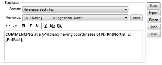
- Select: Use these buttons to select the area of the description you wish to change the template string.
- Keywords: Depending on which template is selected, the keywords pulldown will be filled with valid fields for that type of template. While entering/editing your templates, pull down the list and you will see the keyword along with a brief description of each. Once you choose your keyword, choose the button to the right to paste it into your template. You can also type keywords in directly.
- Toolbar: The controls on the toolbar are the same as for the Results Editor, and explanations can be found in that section above.
Fields:
The list of available fields along with their descriptions are displayed on the dropdown list, relative to the current template.
|
|
Cardinals:
- The [CardMaj] keyword returns four increments being Northerly, Easterly, Southerly, or Westerly.
- The [CardMin] keyword will return these four as well as Northeasterly, Southeasterly, Southwesterly, and Northwesterly.
Note: The field [CardMin] is used in the application defaults to give the general direction a curve is heading.
The parcel related fields of [ParName] and [ParDesc] can be used at any part of the description (header, lines, footer, etc).
†Notes:
- The file DEFAULT.DLD has been made read-only to prevent being overwritten. If you ever need to restore the application to the shipping defaults, you can load it.
- The custom fields of the DwgProps dialog can be referenced. Use the following format: [CusVar:CustomVariableName], for example: [CusVar:TitleCompany].
- The summary fields of the DwgProps dialog can be referenced. Use the following format: [SumVar:SummaryFieldName], for example [SumVar:Title].
- Any CAD system variable can be referenced. Use the following format: [SysVar:SystemVariableName], for example [SysVar:USERNAME].
General Settings:
The following section explains the many options found on the bottom of the dialog.
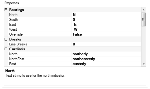
Bearings:
Precision bearings can be formatted using your own words or letters. The most common scenarios are symbols (letters) with spaces like "N " or words like "North". To make it easy to choose these, two buttons are available in this section to quickly populate the fields. The seconds precision is controlled by the Angular Units in the Units Precision section.
If you turn on the [x] Override N/S/E/W toggle, the words will override the corresponding bearing. In other words instead of using N 00°00'00" E the word North will be used. All bearings other than these four directions are not affected.
Note: Cardinal directions can also be used. See the Cardinals section for use of cardinal directions.
DMS Separators:
You can control the separators between the degrees, minutes, and seconds. There are buttons for the most common scenarios of symbols and words. Some descriptions might use a dash.
Units Precision:
You can set independent precision for each of five categories.
- Angular Values: Affects bearings and delta/interior angles reported.
- Course Distances: Affects line and arc distances as well as other reportable fields considered distance.
- Coordinates: Affects only the precision of coordinates, if included.
- Primary Areas: Affects square feet if using imperial, or square meters if using metric fields.
- Secondary Areas: Affects acres if using imperial, or hectares if using metric fields.
- Number Words: Instead of using digits for the results, you can choose to use number words. For example, instead of 123.34 you can have "one hundred twenty three point three four". Turn on the toggles for the categories you want reported in words instead of digits.
- Use Commas: You can designate if numbers 1000 or greater use a comma as a separator.
- Hundredths Words: If this toggle is off, 1.12 will return "One Point One Two", if it's on it will return "One and Twelve Hundredths".
Raw Data:
You can designate whether you want to capture a TDS RW5 file of the calls generated. This could be used to bring into a traverse editor for closure checks.
If you designate the Copy to Clipboard option, you will need to open a notepad or other editor after processing to paste the results. If you use the Write to DWGNAME.RW5 option, it will create a file in the same folder as the drawing, using the same name, but with the RW5 extension.
Note: This should not be used when processing multiple parcels, because the target storage would be overwritten by each parcel.
Description:
You can change the case of found descriptions using one of the supplied options.
The Search Radius field is used to determine the maximum distance from the segment end the program should look for and consider found. Additional information is in the Templates section below under the [PntDesc] field.
Paragraphs:
You can determine the number of line breaks 0-3 after each call. Using:
- (0) will create a single flowing paragraph appropriate for word processors.
- (1) will create a new line for each call.
- (2) & (3) creates double- and triple-spaced documents, respectively.
Cardinal Words:
You can change the text used in cardinal words. One example might be to change the default "northerly" to "North", etc.
Other Strings:
You can change these strings:
- Ending: You can change the ending string from the default of "the point of beginning."
- Passthru: Reports points the segment "passes thru", with optional distance along the segment.
The {PntDesc} subfield reports the description and the {Distance} subfield reports the distance along the segment.