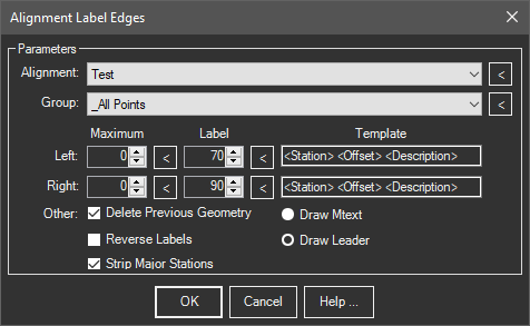
Adds string template based station/offset labels to alignment/sheet edges.
Keyboard Command: AliLabEdg

Procedure:
- Select the centerline from the popdown list or use the button to select it in the drawing.
- Select the point group or click the to create a temporary group.
- Set additional parameters as desired.
- Choose the button to begin processing.
Fields:
- <Station>: The formatted station value. The precision for stations is set in the C3DTools tab of the OPTIONS command in Civil3D, or the Defaults dialog in MapWorks.
- <Offset>: The formatted offset value. The precision for offsets is set by the CAD LUPREC system variable.
- <Point>: The point number obtained from the survey point symbol.
- <Northing>: The northing value obtained from the survey point rounded to the CAD LUPREC variable.
- <Easting>: The easting value obtained from the survey point rounded to the CAD LUPREC variable.
- <Elevation>: The elevation value obtained from the survey point rounded to the CAD LUPREC variable.
- <Description>: The description value obtained from the survey point.
Notes:
- The output can be Mtext objects or Leader (MLeader) objects. Choose the output option desired.
- Labels are created at the current text size specified with the CAD TEXTSIZE system variable.
- The maximum values (first numeric column) indicates the maximum offset to consider for labeling. Points with offsets greater than these values will not be labeled.
- The label offsets distance (second numeric column) indicates the distance for the insertion point of the resulting labels. This may need to be increased or decreased based on the text size used.
- If Delete Previous Geometry is on, it will remove the previous labels for this alignment only.
 Alignment Label Edges