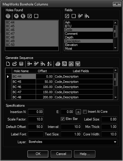
The Geologic Columns dialog allows you to generate detailed labeled columns representing borehole data.
Keyboard Command: GeoBorCol

Procedure:
- Specify the 'Default Offset' desired at the bottom of the dialog.
- Select a borehole in the upper left to add to the sequence.
- Choose the fields to label in the upper right list.
- Choose the button to add it.
- Repeat steps 2 thru 5 as desired.
- Optionally choose the Save icon in the sequence section to save for later recall.
- Specify additional parameters in the bottom section.
- Choose to begin processing.
Notes:
- Borehole Columns are built as block definitions prefixed with "BORE_". You can use AutoCAD's BEDIT command to make modifications to the inserts.
Dialog Sections Detailed:
- Holes Found: This list contains the HOL files found in the search paths.
- Alignment: Allows you to select a polyline to use for determining the offsets (which is the borehole stations along the polyline).
- Add to List: Adds the selected boreholes to the generated sequence list.
- Select: Allows you to select the boreholes in the drawing which selects them in the list.
- Select All: Selects all boreholes in the list.
- Clear All: Clears all selected boreholes in the list.
- Label Fields: This list contains all the fields found in the found holes.
- Select All: Selects all fields.
- Clear All: Clears all selected fields.
- Move Up: Moves the selected row up in the list.
- Move Down: Moves the selected row down in the list.
- Generate Sequence: The spreadsheet and the control icons above it are used to establish the sequence.
- New: Clears the grid to begin a new sequence.
- Open: Prompts for a CSS (Column Sequence) file.
- Save: Saves the contents of the grid to a CSS file.
- Print: Prints the contents of the grid.
- Delete Row: Deletes the currently selected row.
- Move Row Up: Moves the currently selected row up one position.
- Move Row Down: Moves the currently selected row down one position.
- Sort: Sorts the contents of the grid.
- Specifications:
- Insertion N/E: Enter the coordinates or use the pointer button to pick a base location in the drawing. If you turn on the Insert At Core toggle, you can use these two fields to specify the X/Y offsets relative to the borehole location.
- Layer: Enter a layer name or choose an existing layer from the drop down list.
- Scale Factor: Enter the insertion scale desired for the bore blocks.
- Elev Bar: Turn on the toggle if you want to add an elevation bar on the left of the core.
- Label Size: Enter a size for the core name and elevation label. The size is multiplied by the scale to determine the actual label size.
- Default Offset: For single holes, enter the (x) offset from 0, for multiple holes, enter the distance between holes.
- Interval: Enter the distance in feet for the interval to label the elevation bar.
- Min Thick: If labeling of thin strata members causes an undesired overlap in description labels, enter a minimum thickness that the strata item must be in order to be labeled.
- Label Font: Optionally enter a font name to use. Otherwise the current STYLE is used.
- Text Size: Enter a size (in drawing units) for the core elevation bar labels. The size is multiplied by the scale to determine the actual label size.
- Core Width: Enter a width (in drawing units), to determine the width of the corehole in the section plot. The size is multiplied by the scale to determine the resulting core width.
- Layer: Enter a layer name or choose an existing layer from the drop-down list.
 Borehole Geologic Columns