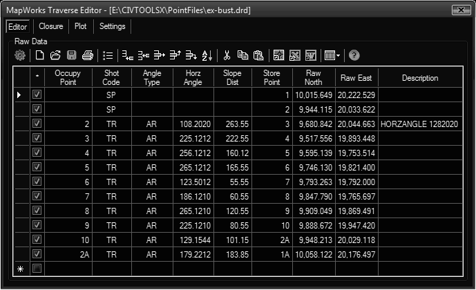
This tool allows typed entry of raw traverse data and importing from multiple formats. It also provides the ability to reduce the data (calculate coordinates) and save the data to a raw file or save as point database formats.
Keyboard Command: PntAddTrv

Toolbar Button Details
The list below describes the toolbar functionality specific to the traverse editor.
- Calculate: Recalculates the coordinates based on the raw data, clearing any balanced coordinates.
- New: Immediately clears the grid. ready for entering new data.
- Open: Opens a raw data file, which immediately replaces the grid contents. The application has its own file format (*.DRD) and supports the basic components of several other formats during import. The following is the list of currently supported formats.
- DotSoft Raw Data (*.drd)
- AASHTO SDMS Project (*.prj)
- Autodesk Fieldbook (*.fbk)
- Tripod Data Systems (*.rw5)
- Leica GSI Raw Files (*/gsi)
- Topcon FC-7/GTS-7 (*.gts7)
- Save: Saves the contents of the grid to a file. The default format is our own format (*.DRD), which stores the entire contents. Other point database options exist for the purpose of transmitting the resulting point coordinates.
Important: The preferred save method is to a DRD file until (and including when) the coordinates are finalized. Then save to a separate point database file.
- Print: Prints the grid contents to a windows printer.
- Comments: Controls whether comments (show code -- two dashes) loaded from a RW5 are displayed.
- Add: Adds a new row at the bottom of the grid for adding another point record. The cell pointer will be placed at the first field, ready to type new data.
- Insert: Inserts a new row above the currently selected row.
- Delete: Deletes the currently highlighted row.
- Move Up: Moves the currently selected row up.
- Move Down: Moves the currently selected row down.
- Sort: Sorts the contents of the grid by point number.
- Cut: Cuts the selected contents to the clipboard, which blanks out the grid area.
- Copy: Copies the selected contents to the clipboard, the grid area remains intact.
- Paste: Pastes the contents from the clipboard to the grid area.
- Autosize: Resizes the grid contents to accommodate the current contents.
- Hide Cols: Brings up a small dialog allowing you to hide columns that are not applicable to the current entry. For example when entering deeds, fields like backsight and instrument/rod heights are not needed.
Procedure:
- Initiate the tool.
- Click the button, turn on only the columns applicable to the raw data.
- Click the button to add a new row.
- Begin entering acceptable values, pressing Enter or Tab to go to the next column.
- Periodically click the button to save your data to a DRD file.
Notes:
- During the entry of the row data, press Enter to go to the next column. At the end of the row pressing Enter begins a new row at the first column.
Supported Codes
The following two letter codes are valid in the Shot field.
- SP Store point with coordinates supplied.
- TR Traverse to the point with raw data supplied.
- SS Turn a sideshot to the point with the raw data supplied.
The following two letter codes are valid in the Type field.
- AZ North Azimuth in DDD.MMSS format.
- AL Angle Left in DDD.MMSS format.
- AR Angle Right in DDD.MMSS format.
- DL Deflection Left in DDD.MMSS format.
- DR Deflection Right in DDD.MMSS format.
- NE Bearing in the NorthEast quadrant. The following bearing is in DD.MMSS format.
- SE Bearing in the SouthEast quadrant.
- SW Bearing in the SouthWest quadrant.
- NW Bearing in the NorthWest quadrant.
Calculating Closure
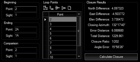
To calculate the closure, first choose the button to calculate the raw coordinates, this activates the button. The Closure dialog appears (shown below).

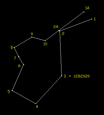
The beginning, ending, and comparison points are required to calculate closure. This allows for closure checks back to the point of beginning or to other pre-established points. However the sight fields are only required if you wish to calculate the angular error. The following graphic (in conjunction with the closure dialog) can help demonstrate how the closure dialog works. This traverse example was intended to close poorly.
Closure Procedure:
- Choose the button to initiate the closure dialog.
- Enter the beginning, ending and comparison point numbers.
- If you want to calculate the angular error, enter the beginning, ending and comparison sight numbers.
- Click the button to automatically populate the Loop Points grid.
- If necessary, edit the points in the Loop Points grid using the toolbar buttons.
- Choose the button.
Graphic Example

Plotting Traverse Data
After calculating coordinates, you can plot the traverse data in the current drawing. Choose the button and the following dialog appears.

Simply choose the options you wish to plot using the toggle on the left and optional layers or linetypes using the popdowns.
Settings Tab
This tab shows options for the traverse dialog.
 Point Traverse