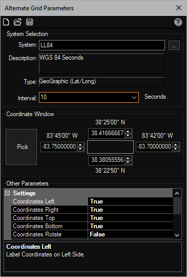
Draws a bound collection grid lines (and labels) in an alternate coordinate system.
Keyboard Command: PrjAltGrd

Procedure:
- Open the drawing containing the area to process.
- Initiate this tool from the menu, ribbon or command above.
- Enter the alternative system code or use the button to select it.
- Enter the desired interval or select it from the list.
- Pick the area you want the grid to cover (see note).
- Confirm the coordinate window below and make changes as desired.
- Conform other settings in the bottom of the dialog.
- Click the button at the top to generate the grid.
Notes:
- After picking a window, the corners are projected to the chosen system and the values rounded to the interval specified. As such the resulting grid may be slightly larger than the window picked. You can use the arrows on the value fields to increase or decrease these values by the interval chosen.
- You can use the button to clear the dialog and start again, or use the button to select an existing alternate grid. After opening an existing grid the parameters used on that grid are shown, you can make adjustments then save the changes to the opened grid.
- For the Draw Geometry Color, you can enter 0 for ByBlock, 256 for ByLayer, or any number in between to represent a color. Using 0 is recommended.
- By default, alternate grids are drawn on a unique layer and that layer is locked. This prevents the moving of an alternate grid, which would lead to erroneous coordinates.
 Projections Alternate Grid