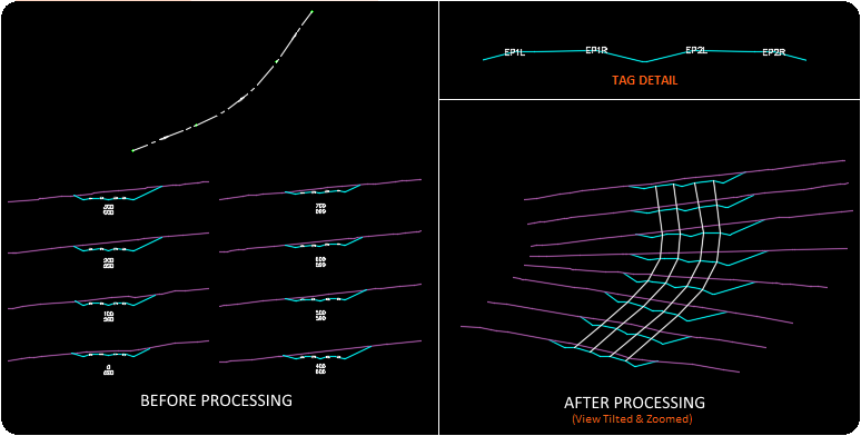
Convert cross sections to plan view 3D Polylines along an alignment and optional surface. Requires a centerline alignment and sections (as polylines). All the polylines used to create a surface must be in one layer. For example if a EG/FG scenario exists, all the existing ground section polylines must be in one layer (example EG) while all finished ground polylines reside in another (example FG).
Keyboard Command: SurCnvSec

Procedure:
- If the desired station interval does not match the interval echoed on start, use the Interval suboption to set it.
- Use the Tag option to place the (mtext object) tags which will indicate the reference station and elevation.
- Optionally use the Breaks option to place breakline text on the sections which will form breaklines during the processing.
- Issue the process option to evaluate the section polylines, mtext tags, and break text.
SubOption Details:
- Breaks: Prompts first for the text string to use (such as EPL), then prompts repeatedly for the location to place that label. Pick each section polyline endpoint at the corresponding location (placing the label only once on each polyline). Press enter when finished then use the command option again if you have additional break text to place.
- Interval: Prompts for a numerical interval value, used to speed up the tagging process.
- Process: Prompts first to select the alignment, then the Section Polylines, Break & Tag Annotation. Last prompt is for an exaggeration value other than <1.0>.
- Tag: Prompts repeatedly for a mark point, station, and elevation. The mark point should be the zero station position on the section, pick that point. The station prompt should provide the correct elevation allowing you to simply press enter. For the elevation prompt you may need to enter the elevation at the point picked.
Notes:
- When processing, the tag (mtext object) nearest to the center of the polyline will be used for the polyline.
 Surface Convert Sections