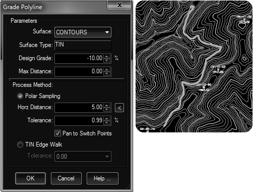
Generates a 3D Figure along a surface at a given design slope. The routine uses an interactive approach. When it can't find a logical looking forward path or reaches the edge of the surface, it stops and shows the users arrows of paths that can be taken. The user can pick in one of the directions or press enter to end. When it reaches a point where the surface flattens out it stops and generates the figure.
Keyboard Command: SurGrdPth

Procedure:
- Open the drawing/project containing surface definition.
- Initiate the tool.
- Select the surface from the pop down.
- Specify the design grade.
Use a negative value to go down hill, a positive value for uphill. - Specify the distance between vertices.
Notes:
- While the tool is processing, the current elevation reached is shown at the bottom of the CAD window (also helps determine it's progress).
- A larger horizontal distance can speed up the process but makes for a more coarse polyline.
- Do not attempt to start the process on a flat area, such as a surface made from contours. For example, picking inside the contour to the right of the starting point would be a flat area.
- If you wish to limit the length of the result, specify a max distance value. Leaving the value at zero will produce the longest path possible.
 Surface Grade Figure