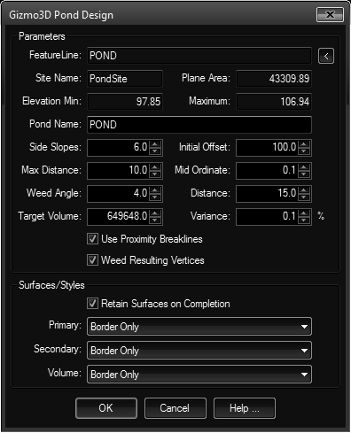
Design a pond using a starting FeatureLine, specified side slopes and desired volume. Creates the other FeatureLine, two TinSurfaces and a VolumeSurface.
Keyboard Command: SurPndDes
This tool begins by creating a temporary surface using the selected FeatureLine and an offset (at the initial offset distance). It then extracts a contour at the top elevation of the FeatureLine and continues to move that up the sides until the target volume is reached.

- FeatureLine: The name of the selected FeatureLine. The (uneditable) fields adjacent to the FeatureLine show the site, area, minimum and maximum elevation of the FeatureLine.
- Pond Name: This is the base name for the resulting surfaces. The name will contain PRImary, SECondary and VOLume suffixes.
- Side Slopes: The ratio (to one) to use for offsetting the geometry. Larger numbers indicate gentler slopes, smaller numbers indicate steeper slopes.
- Initial Offset: This is the maximum horizontal distance to consider. This distance is used along with the side slopes to determine the initial structure. Make sure this value is adequately large enough so that the final FeatureLine will reside inside of it. This temporary offset FeatureLine is removed before the tool completes.
- Max Distance: This value is supplied to Civil3D in building the surface(s) and defaults to the same value used in Civil3D's own add breaklines to surface dialogs.
- Mid Ordinate: (see above)
- Weed Angle: (see above)
- Weed Distance: (see above)
- Target Volume: The desired volume (in cubic current drawing units). For example, if the current drawing is in feet, this requires cubic feet. Be sure the specified value is adequate enough to generate a FeatureLine above the top elevation of the bottom FeatureLine. The initial value is fifteen times the selected FeatureLine area.
- Variance: The percent variance acceptable so the tool does not attempt to match the exact volume. The small default of 0.1% should allow the tool to complete within the built-in maximum of ten iterations.
- Breaklines: When this toggle is on, the tool will create temporary proximity breaklines that run between the selected FeatureLine and the initial temporary offset. These run somewhat perpendicular to the selected FeatureLine (bisecting at each vertex). This can help the resulting FeatureLine conform to the correct path.
- Weeding: Since the resulting FeatureLine is essentially an extracted contour, this option weeds the resulting FeatureLine (using our own weeding method).
- Styles: If you choose to retain surfaces when the process is complete, you can determine the surface styles to use. The default is border only for all three.
Procedure:
- Open the drawing containing the pond bottom FeatureLine.
- Initiate the tool.
- Click the in the upper right and select the FeatureLine.
- Specify additional parameters as desired.
- Click the button to begin processing.
Notes:
- If this tool cannot obtain the target volume within ten iterations it will stop and report the condition. Civil3D builds a lot of temporary files during the iterations but these will be cleared under normal closing of the application. It is a good idea to inspect the contents of your TEMP folder periodically (at least weekly) when running Civil3D.
 Surface Pond Design