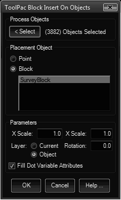
Insert on Objects will automatically place a local block on the definition points of a selection set of objects. The routine presents you with a list of all of the blocks currently defined in the drawing. If Point is chosen, a point object will be placed instead of a block. This function can place the insert on 3DFACE corners, ARC endpoints, CIRCLE center points, ELLIPSE centers, LINE endpoints, MTEXT insertions, POINT nodes, POLYLINE vertices, SOLID corners, and TEXT insertion points.
Keyboard Command: BlkInsObj

Procedure:
- Initiate this command from the menu, ribbon, or command above.
- Select desired insert from the list, only one may be selected.
- Specify the desired scale factors and rotation angle.
- Designate the insertion layer. The current layer can be used, or the layer of the object on which the insertion is placed.
- If the block definition selected contains attributes, specify if the insert should pick up object values (see below).
- Select the objects to place the insert object on.
If Yes is specified in step five, and the block definition contains attributes with the proper tag names, the routine will pick up and assign these values to the attributes as they are being inserted. To utilize this feature, simply give your attributes the following tag names when you define them in AutoCAD. This can be useful for spot elevation blocks on points, coordinate labels on polyline vertices, etc.
- .INSPTX: Point X Value
- .INSPTY: Point Y Coordinate Value
- .INSPTZ: Point Z Coordinate Value
- .LAYER: Object Layer
- .THICKNESS: Object Thickness
Notes:
- If the AutoCAD Point option is chosen, it will honor the current settings of the PDMODE and PDSIZE variables.
- To use the ToolPac PT### blocks listed in the previous versions, simply drag the DWG file from the \Data folder to the AutoCAD editor, then press ESC when prompted for an insertion point.
 Block Insert On Objects