ToolPac has several options that can be set. These options can affect one or more parts of the ToolPac program, and are explained below.
Keyboard Command: GenSysDef
General Tab:
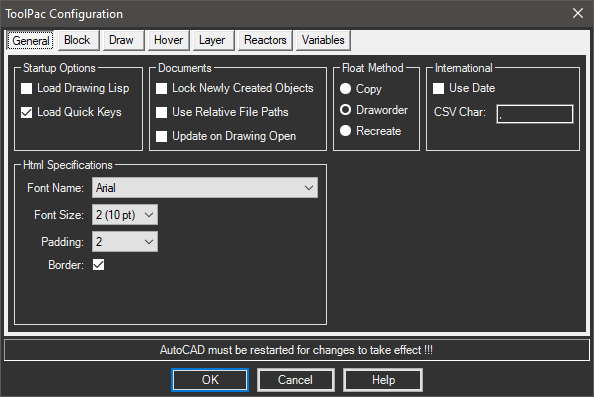
- Load DWG Lisp: If this toggle is turned on, and a lisp file exists in the same directory and has the same filename as the drawing, it will be loaded after the drawing is completely loaded.
- Load QuickKeys: If this toggle is turned on, the alias definition file QUIKRUN.LSP will be initialized on startup. As some of ToolPac's aliases conflict with aliases from other third party programs, you may want to clear this toggle so ToolPac's aliases do not load. ToolPac's tools can still be initialized from the pulldown menu or toolbars.
- HTML Specifications: The values set here control the appearance of ToolPac's HTML generated reports. Many tools that generate tables of results present a list of choices which include the HTML In Browser option as explained above. These settings also affect the Layer Table to Browser option.
- International:
- Date: Turning on the date toggle will cause ToolPac to generate the date in the form of DDMMYYYY.
- CSV: Allows you to change the character used in file exports that normally use commas. As the comma can mean the decimal point in some international environments.
- Float Method: Designate the method of floating geometry. Only the draworder method can preserve associativity hatches.
- Dialogs: Many of ToolPac's dialogs have normal and large versions. Large versions typically have many more items visible on lists, etc. Many of the newest dialogs are resizable.
Block Tab
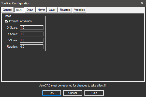
- Block Insertion: When ToolPac's block insertion routines are used, they will not prompt you for scale factors, but will use the values shown. If you want ToolPac's routines to prompt for any or all of these parameters, simply clear the contents of the edit field.
Draw Tab
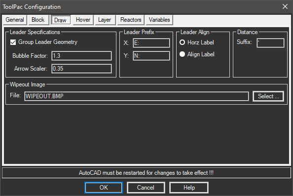
- Leader Specs: Controls the appearance of leaders created using ToolPac.
- Group Geometry: If the toggle is turned on, the routines will bind all leader vectors, arrowheads, and annotation into a single anonymous group for easy movement or deletion.
- Bubble Factor: This is the factor of the bubble circle to the current text height. You may need to increase this factor if the number of characters in the bubble label exceeds two characters.
- Arrow Scaler: Controls the size of the arrowhead placed on the end of ToolPac's polyline leaders. This percentage value is multiplied by the current text size.
- Leader Prefix: These fields are applied to coordinate leaders.
- Distance Suffix: The characters appended to distance annotations.
- Leader Align: The default behavior is to create the leader annotation horizontally on the drawing. If the align option is chosen, the annotation will be rotated to align with the last two points of the leader.
- Wipeout Image: This is the image file (default is a BMP of 66 bytes) used by ToolPac to achieve masking.
Hover Tab
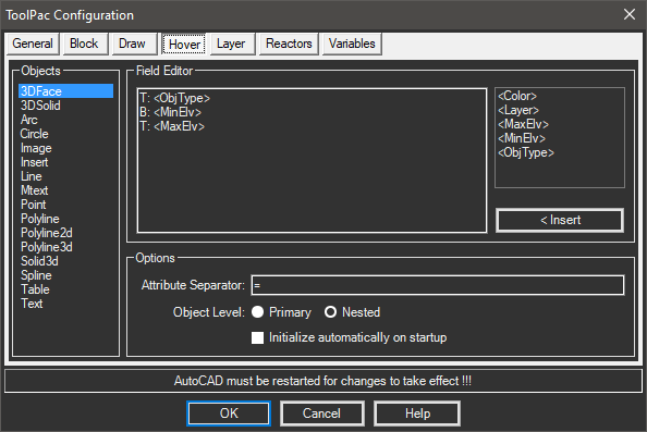
- Objects: Select the item to change in this list.
- Field Editor: Edit the hover text template in this area, fields that can be inserted are shown to the right.
- Options: Various options related to the hover reporting.
Layer Tab
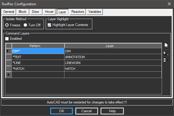
- Layer Isolation: When ToolPac's layer isolate routine is run, it can isolate by freezing or turning off layers. If freeze is used, AutoCAD will require a regen when the layers are restored, which can take time. Although the off method is usually faster, routines that select objects can accidentally manipulate objects in layers that are off, since they have been generated.
- Layer Highlight: Affects several of ToolPac's layer routines such as lock, freeze, and off. When highlight is turned on, all objects in a picked layer will be highlighted, verifying objects subject to manipulation. This can be a useful effect except in extremely large drawing where the highlight can slow down processing.
- Command Layers: This area lets you control the status of command layers, as well as adding/editing of the commands reacted to.
- Add: Adds a blank line at the bottom of the grid allowing you to type in a new assignment.
- Delete: Deletes the row currently selected.
- Clear: Clears the contents of the grid, consider saving first.
Note: These settings are stored in CmdLayer.dat in the
ToolPac\Datafolder.
Reactors Tab
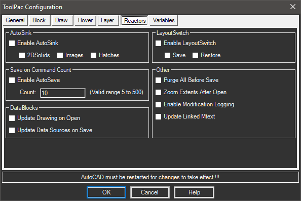
- AutoSink: Sends newly created (semi) opaque geometry to the bottom as they are created with any command. This includes 2DSolids, Images and Hatches.
- LayoutSwitch: Automatically saves the layer state of the current layout before switching, then restores the layer state of the selected layout.
- Command Save: The best approach to saving is to develop a good work habit of issuing the save command when you have accomplished something in the drawing. If this reactor is turned on, it will automatically save the current drawing when you have issued the specified number of commands. The save results are exactly as if you had issued the save command.
Note: Use this option with extreme caution, it will save every drawing after the command count is reached, which may not be desirable! It is highly recommended that you turn this option off and restart AutoCAD before running scripts.
- Other:
- Purge All: Runs the standard AutoCAD purge all three times before the drawing is saved, with no visual noise at the command prompt.
- Zoom Extents: Automatically zooms to the extents of the drawing after its opened.
- Mod Logging: Adds a new record in the DWGPROPS Custom section when a drawing is modified and saved. This allows administrators to review a history of who modified the drawing and when. The record is in the format of LOGINNAME (UNIQUEKEY)=SAVEDATETIME. Only one record is created per editing session.
Note: The UNIQUEKEY value is required as AutoCAD will not allow more than one record with the name name.
Variables Tab
This page deals exclusively with the setting of common variables when each drawing opens. Often users receive drawings from outside sources and wish variables to be set to their liking. By using this panel to set up the values you want, ToolPac will set these variables whenever a drawing is opened. Each section of the dialog is explained in detail in the section following the dialog example.
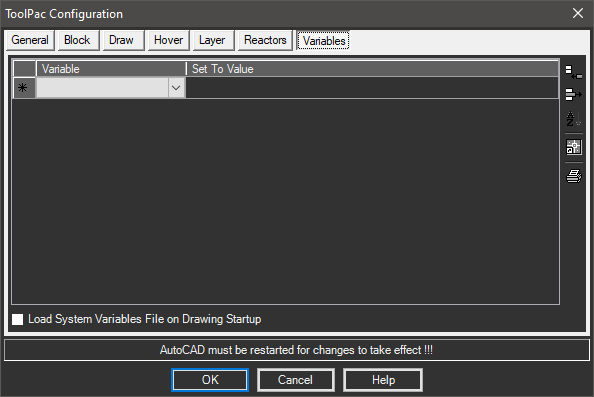
Procedure:
- Choose the button to create a new row.
- Activate the pulldown list and choose a variable name to set.
- Double click the second column to begin typing a value to set.
Note: You can choose the button to fill the field. This can help determine the appropriate format for 2D/3D points.
- Repeat steps 1 through 3 as desired.
- Choose the button to close and save changes.
- Grid: Contains the variables and values you wish to set, one variable per row.
- Buttons:
- Add: Adds a new row at the bottom of the grid.
- Delete: Deletes the currently selected row(s).
- Sort: Sorts the grid based on the variable name.
- Current: Fills the set to field with the current value of the variable.
- Print: Prints the contents of the grid to a Windows system printer.
- Details: The section at the bottom displays details about the variable name you are setting, a description and other information is displayed. You may need to scroll the bottom grid to see this information.
- Load: This toggle allows you to turn the system on or off without affecting the variables you have stored.
Notes:
- A handful of AutoCAD variables are in 2D/3D points and must be entered as comma separated values. Note the GRIDUNIT and INSBASE values in the dialog above.
- Using this function (even with only one variable) will cause the drawing to be considered changed on startup. Therefore you will get a message from AutoCAD that the drawing has changed if you attempt to close it.
- The contents of this grid are stored in a file named TOOLPAC.VSF which does not exist until you create it. Initially the file is created in the \ToolPac folder. If you move the file to another folder that exists in the support paths, ToolPac will read from (and later rewrite to) that location.