 Create New
This tool is used to place a new document in the drawing.
Keyboard Command: WD2CADCN
Before you can place a new document in the drawing, these steps should be followed.
Prepare CAD:
- Open your target drawing (if not already open).
- Set the appropriate space (model or desired layout).
- Set the desired Layer.
- Set the current text style if you don't plan to use the true-type fonts as shown in the document.
Prepare Word:
- Launch Word.
- Open your existing named document.
- Highlight the area you want to transfer.
Note: You do not need to choose Copy. This tool reads the document through the ActiveX channel, it does not use the Windows clipboard.
Placing the document:
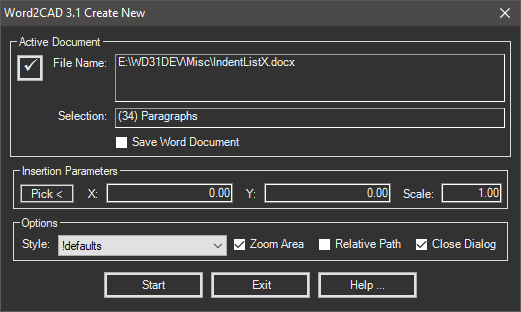
The sections of the create new dialog are explained below.
- Active Document: If you have already prepared Word, the top portion of this dialog will be filled in with information quickly obtained from Word as it is launched. If you haven't prepared Word, use the procedure above, then choose the button in the upper left. This can also be used when creating multiple documents without leaving this dialog. Simply change Word files/sheets/ranges then choose the button before continuing.
- Insertion Parameters:
- Pick: Use this button to pick a location in the drawing. The picked point will be the upper left corner of the results. The coordinates of the picked point will be displayed in the adjacent fields.
- XPos: If you didn't pick a point, type in the X coordinate of the upper left corner.
- YPos: If you didn't pick a point, type in the Y coordinate of the upper left corner.
- Scale: Determine the appropriate scale factor using these guidelines. Keep in mind that the units in the document are printer points and the unit in CAD can be inches, feet, meters, etc.
Given a scale factor of 1.0 (the default) then (1 point) = (1 unit) in CAD. That means that if you have grid lines on a document at the Word default of 12.75, then it will be 12.75 units inside the drawing (again with a scale factor of 1). While this is *exact* on grid lines, you can't judge text heights the same way because the distance is from top of the highest character (like ') to lowest (like "g" with descenders).
So here are a couple of target sizes, you may like smaller or larger depending on your situation. Most of which are CAD supplied samples.
- Default CAD prototype = 0.025
- 1st floor architectural.dwg = 0.100
- City base map.dwg = 20.000
- Wilhome.dwg = 1.000
- Topographic Mapping = 10.000
- Paper Space in General = 0.010
So it depends on the type of drawings you do. If in doubt, before insertion draw a vertical line (in your CAD app) that is 12.75 units high. This represents the height of one typical row at a scale factor of 1.0.
- Options:
- Style: Select the desired style named. Styles are explained in the Style Manager dialog.
- Zoom Area: If this toggle is on, the CAD viewport is zoomed to the extent of the newly created document.
- Relative Path: Turn on this toggle if you wish to use a relative path. When toggled the displayed file will change. Note that if there is no relative path, such as the drawing and document being on different drives, no relative path can be derived.
- Save Document: Turn on this toggle if you want Word2CAD to save your document for you as the instance is being placed. This toggle is turned off by default because we feel it is best that the user saves the document themselves. There may be multiple ranges to be placed making this inefficient and there may be times when the user does not want the document saved!
- Buttons: The buttons at the bottom perform the following functions.
- Start: Begins communicating with Word and generating the document. Another dialog will appear that displays the progress as well as the type of activity (reading, optimizing, drawing, etc). If you decide to stop the process choose the Cancel button on the processing dialog.
After the document is generated you will be returned to the Create New dialog where you can prepare another document if needed.
- Exit: When you are done creating documents, choose this button to return to the drawing editor.
- Start: Begins communicating with Word and generating the document. Another dialog will appear that displays the progress as well as the type of activity (reading, optimizing, drawing, etc). If you decide to stop the process choose the Cancel button on the processing dialog.
After placing the document:
To provide a link back to the area you selected in the document, it was necessary for this tool to create a named range in the document. Since the document was modified with this information, it needs to be saved.
The amount of time you take to save the document can also affect updating. See the Save Delay section of the System Defaults dialog.
Note: Failure to save the document after placing the document will prevent Word2CAD from being able to update it later.
Additional Notes:
- While Word2CAD is evaluating tables, the progress bar will not change. It evaluates the entire table before generating it. When the program begins to generate the table cells, the progress bar will begin to move.