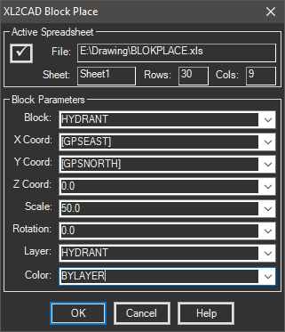
This tool quickly generates block inserts with attributes directly from the Excel spreadsheet. The flow of information is from Excel to AutoCAD and it is not linked.
Keyboard Command: XL2CADTBP

Procedure:
- Open the target drawing in AutoCAD.
- Open the source spreadsheet.
- Highlight the range containing the block data.
- Launch the Block Place tool.
- Wait for the routine to collect your data from Excel.
- For each field in the Block Parameters section, choose a field from the table containing the value to use, or type in a value to use for all inserts.
- Choose the button to begin placing inserts.
Notes:
- The block definitions needed must already be loaded into AutoCAD. This routine will not load them from disk.
- You can place multiple block definitions by using a field in the data source for the blockname.
- There must be fields in the spreadsheet to determine the X and Y coordinates of the insert.
- If you have a large number of rows (or columns) step 5 may take a few seconds. It is collecting all the data from Excel in preparation for drawing.
- In the case of fields like scale and rotation, you can type them in if desired.
- Fields from the external data source are enclosed in square brackets. In other words, the Block field may contain block names contained in the drawing (without brackets) and fields from the database (with brackets).
- While the dialog allows you type in values for X/Y coordinates, the use of this would be extremely rare. The more logical approach is fields in the external data source used as the coordinates.
- All attributes with tags matching field names in the data source are automatically filled in.
 Block Place