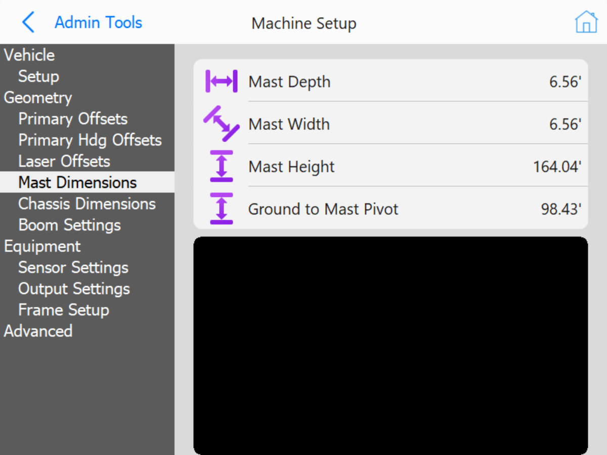
Mast Dimensions: These dimensions are for icon scaling.
Mast Dimensions
Mast Depth: Length of mast depth.
Mast Width: Width of mast.
Ground to Mast Pivot: Distance from ground to Mast pivot point (pivot for tilting mast for transport).
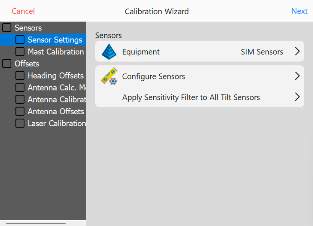
Sensor Settings: Sensor type selection, mounting location (placement), and orientation setup. Includes slope sensors and distance lasers. Laser Distance sensors will be CAN based (located in Configure Sensors menu) or Serial (COM) based hardware.
Sensor Settings
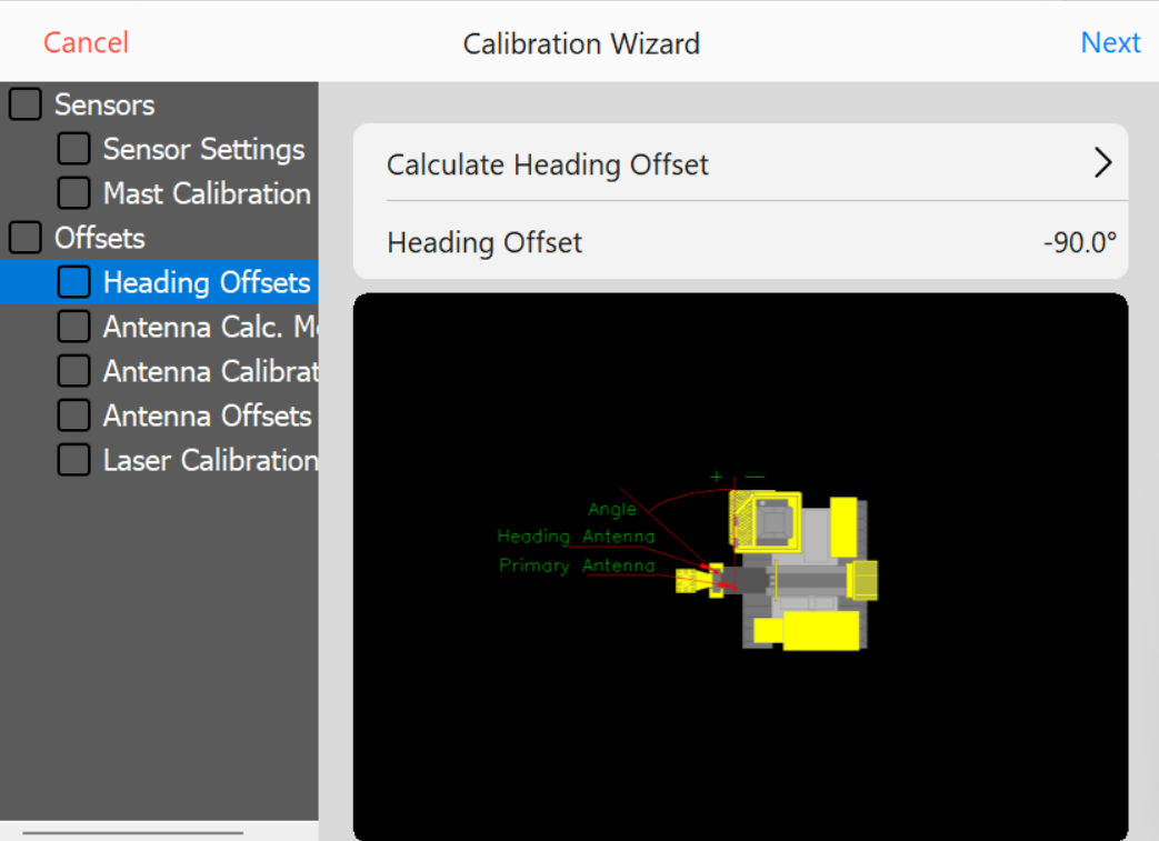
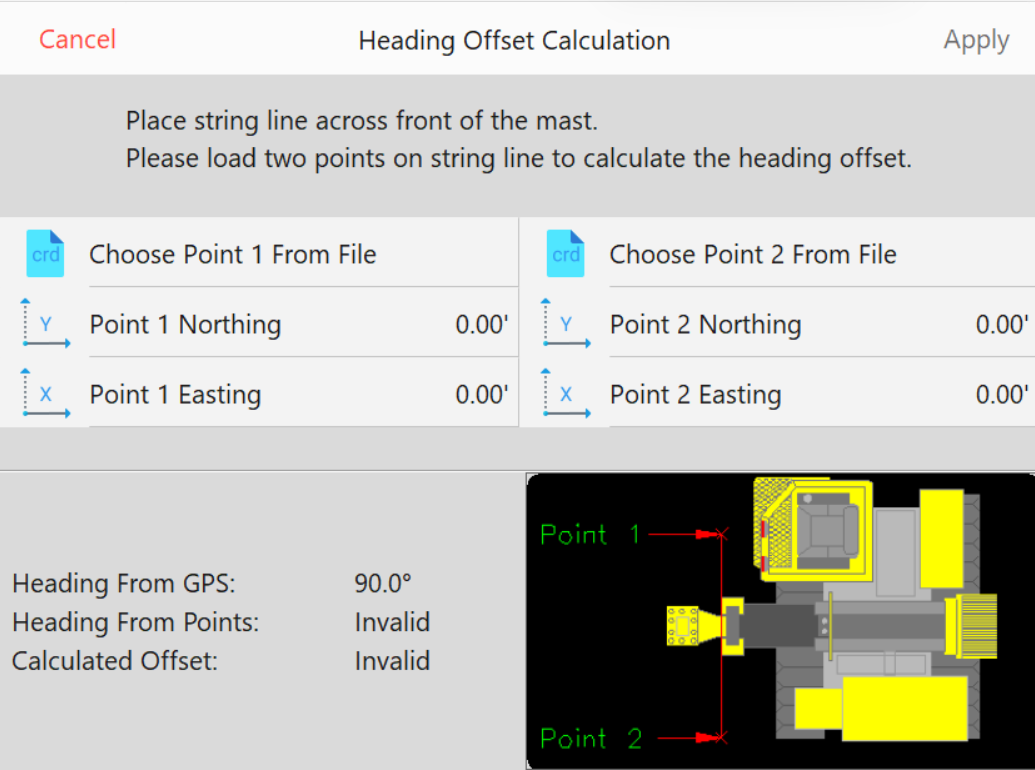
Heading Offset: Calculate Heading Offset using string line or laser level to square machine mast with 2 collected GPS rover coordinates.
Heading OffsetHeading Offset Calculation
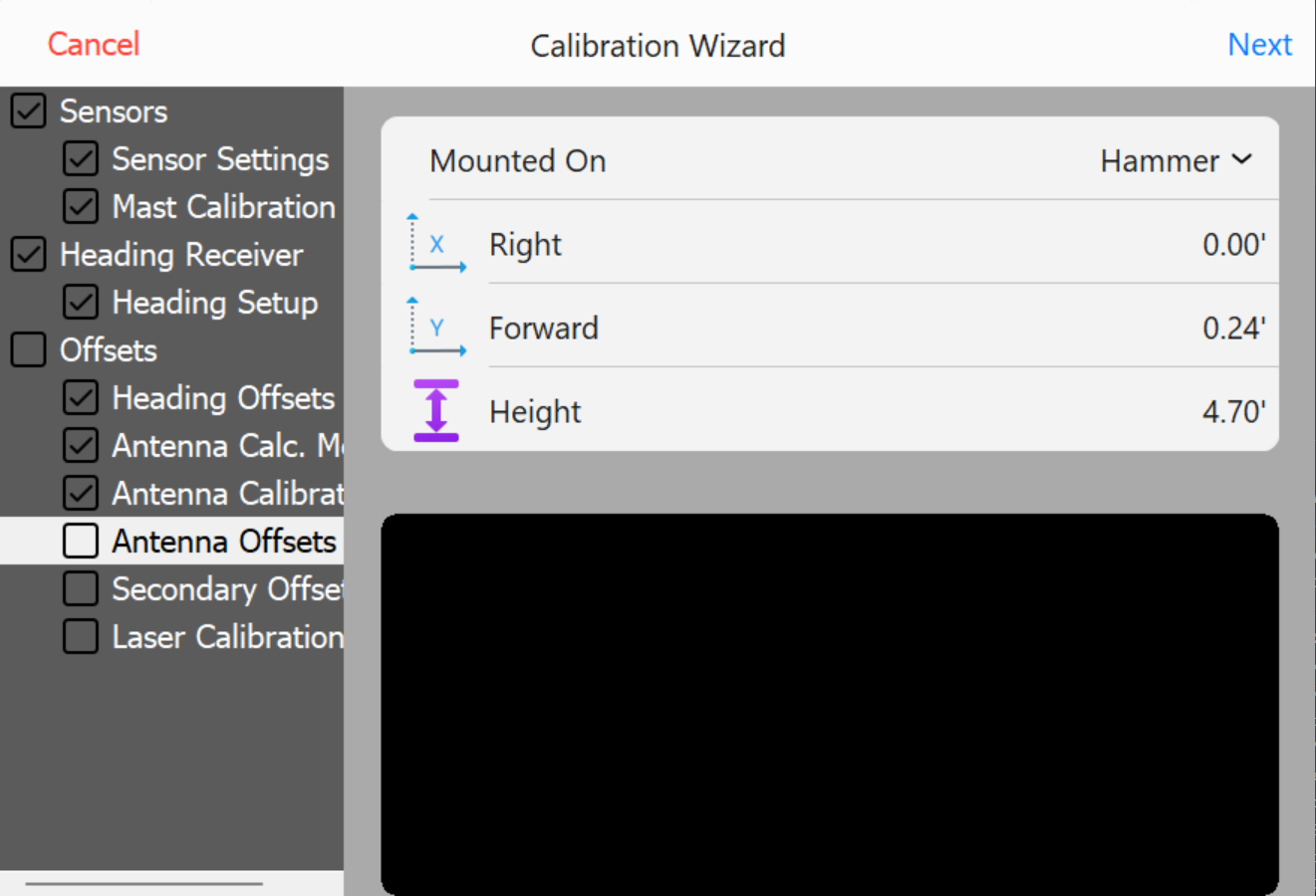
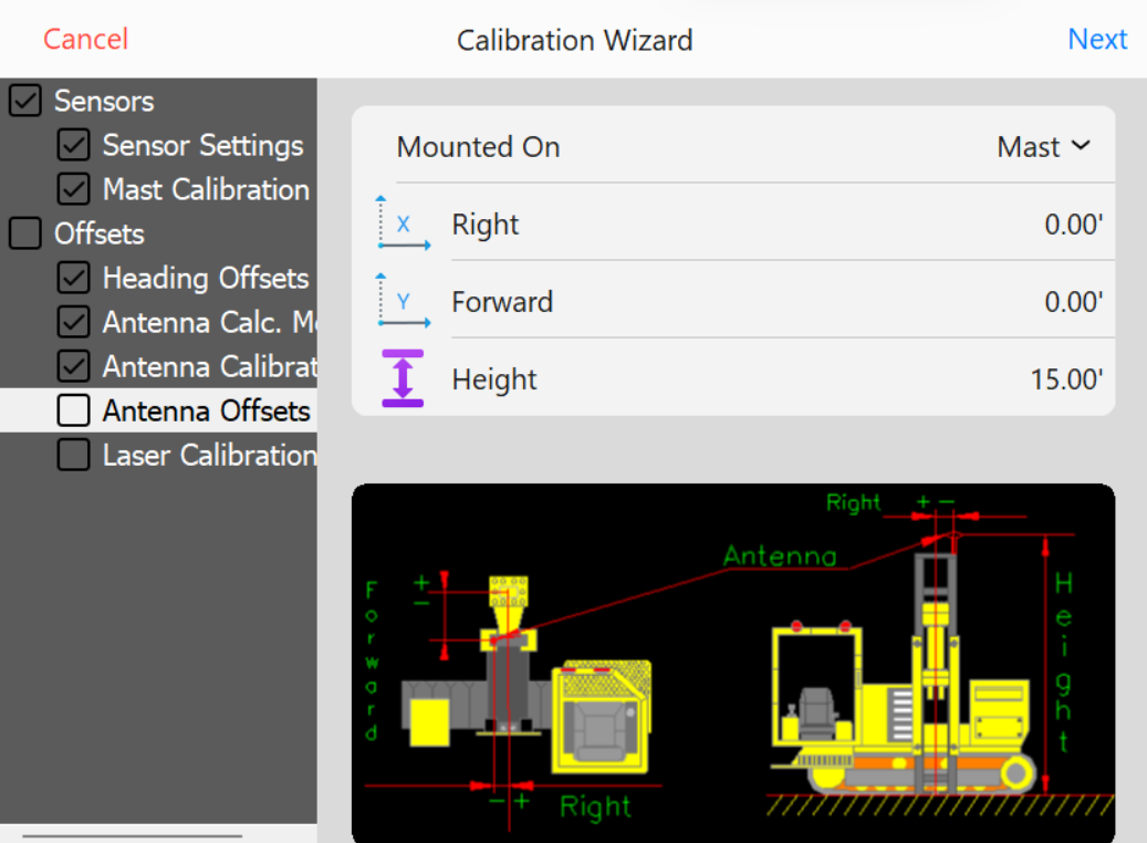
Antenna Offset Calibration
Note: Survey rover is required to calibrate Hammer Antenna Height. Using a survey rover, place the survey rover on Top/Center on the installed pile. Remove any Rod Height values in the data collection software and set to 0.0. Set survey rover antenna to read from base of receiver. Record the NEZ (Northing, Easting, Elevation) at top/center of pile using the survey rover.
Note: Hammer Antenna is machined to locate directly above the center of the striker plate. Right & Forward Offset should be 0.0 or close to 0.0 if the hammer and mast are parallel with one another. As hammer bushings, pucks, and shims show wear, the Right/Forward offsets may show a slight offset in the calculated values.
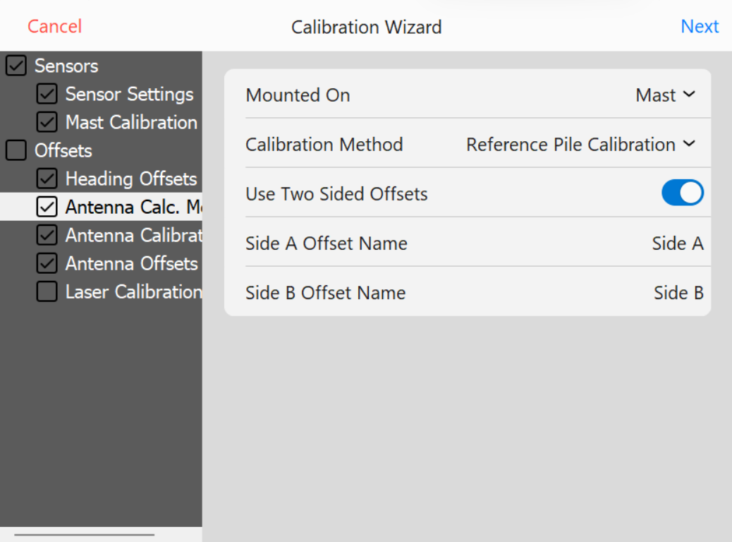
Use Two Sided Offsets: Two sided offsets may only be used if running C Channel piles, if seeing discrepancies in row to row accuracies, or Custom Guides that do not center piles beneath the center of the striker plate. If Two Sided Calibration Method is selected, once you have calculated Side A antenna offsets, you will be prompted to move to the opposite side of the pile (180°) to calculate and record Side B offsets.
Antenna Calculations - Two Sided
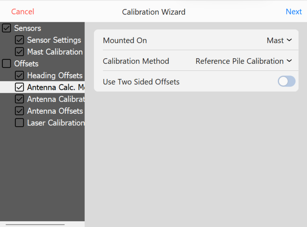
Single Side Calibration: Leave Use Two Sided Offsets unchecked to select single side calibration. This will remove Side A & Side B from Calibration Wizard.
Antenna Calculations - Single Side
Calculate Height: Select this option to calculate a vertical offset distance between Hammer Striker Plate and Hammer GNSS Antenna.
Calculate Forward: Select this option to calculate a Forward/Back horizontal offset distance between center of Hammer Striker Plate and Hammer GNSS Antenna.
Calculate Side: Select this option to calculate a Right/Left horizontal offset distance between center of Hammer Striker Plate and Hammer GNSS Antenna.
Once you have selected offset options to calculate, press NEXT.
If Calculate Height is the only selected option, the software will prompt you to lower Float the hammer on top of the calibration pile.
Float Alert
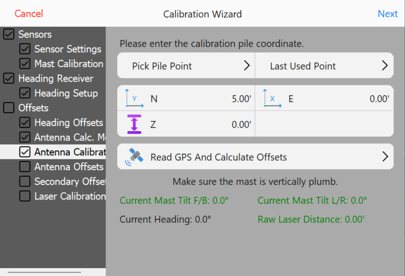
Select which offsets should be calibrated. Calibration will only apply to selected offsets
Enter the surveyed Northing, Easting, and Elevation of the pile and press Read GPS and Calculate Offsets.
Elevation to Read
Then press Next.
Offset will be calculated and populated.
Calculated Offset
Press OK.
Calibration is Complete.
Check Calibration
Check Calibration XYZ (Easting, Northing, and Elevation)
When checking XYZ, survey the center of the pile that will be used to check calibration.
Check Offsets
Enter surveyed N,E,Z from the Center of the pile.
Press Calculate XY Deltas.
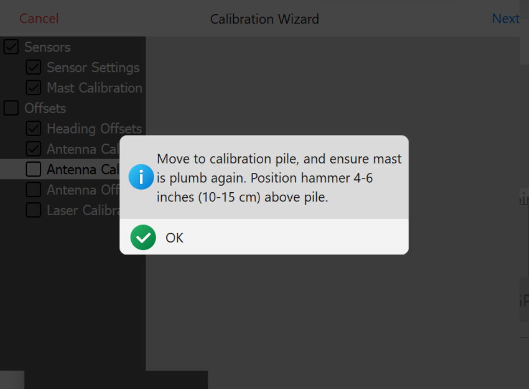
The software will prompt you.
position the hammer centered 4"-6" above the pile.
Level Mast to within ±0.1°.
Hammer should NOT be loaded onto the pile when checking XY. If the weight of the hammer is on the pile, this will cause hammer antenna horizontal offset errors during the calibration check.
The deviation between surveyed point and Hammer position will be calculated in the Right and Forward Delta values.
Check Calibration Z (Elevation)
When checking Z, survey the center of the pile that will be used to check calibration.
Check Z (Elevation)
Enter surveyed Z from the Center of the pile.
Press Calculate Z Delta.
The software will prompt you to lower Float the hammer on top of the calibration pile. Ensure the hammer is loaded onto the pile.
Level Mast to within ±0.1°.
Press OK.
The deviation between surveyed point and Hammer position will be calculated in the Height Delta value.
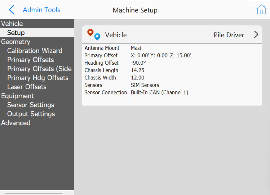
Configure Vehicle
The configuration menu is structured as a tree-list on the left, allowing selection of different setting categories.
Selecting a category opens its specific settings.
Note: This section is intended for qualified installers. If you encounter issues, contact your Carlson representative. This documentation serves as a reference only.
Note: This section contains general information about the Configure Vehicle menu. For individual vehicle type instructions refer to the installation manual for each vehicle.
Configure Vehicle
Vehicle
Pile Driver: Single receiver setup with positioning and heading from two antennas on the mast with a distance laser targeting the hammer, inclinometer on the mast.
PD10 Hammer GNSS: Vermeer PD10 dual receiver setup with heading from two non-RTK antennas on the mast, hammer position and elevation calculated from antenna mounted on the hammer, inclinometer on the mast.
PD10 Enhanced Z: Vermeer PD10 dual receiver setup with heading from two RTK antennas on the mast, XY hammer position from the hammer antenna, Z hammer position from the primary heading antenna and a distance laser targeting the hammer, inclinometer on the mast.
PD5 Hammer GNSS: Vermeer PD5 dual receiver setup with heading from two non-RTK antennas on the mast, hammer position and elevation calculated from antenna mounted on the hammer, inclinometer on the mast.
Hercules Pile Driver: Hercules STR20 or STR18 setup with positioning and heading from two RTK antennas on the mast, sensor data from Hercules CAN (J1939 or CANOpen).
Crane Piler: Cable Crane with a mast tower attached, positioning and heading of the mast and hammer from two RTK antennas mounted on the mast with a distance laser targeting the hammer, inclinometer on the mast. Additional positioning and orientation of the crane available via additional RTK antennas and inclinometers.
Mastless Crane Piler: Cable Crane with vibratory hammer at the end of the cable, positioning and heading of the hammer from two RTK antennas mounted on the hammer. Additional positioning and orientation of the crane available via additional RTK antennas and inclinometers.
Ojjo Truss Driver: Ojjo Truss Driver with two RTK antennas mounted on the mast, inclinometer on the mast.
PD25: Vermeer PD25 dual receiver setup with heading from two RTK antennas mounted on the engine compartment, single RTK antenna on the hammer, sensor data from Vermeer CAN.
Orecto Integrated: Orteco pile driver with RTK antenna on the hammer and RTK antenna on the mast, sensor data from Orteco integration.