The Advanced Tools section is primarily used by Carlson Machine Control representatives and dealers. It allows for the configuration of key system components, including:
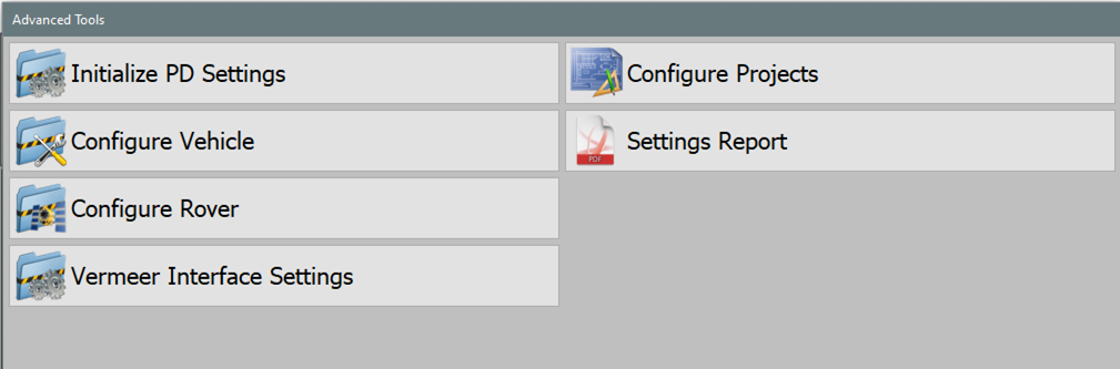
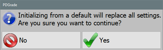
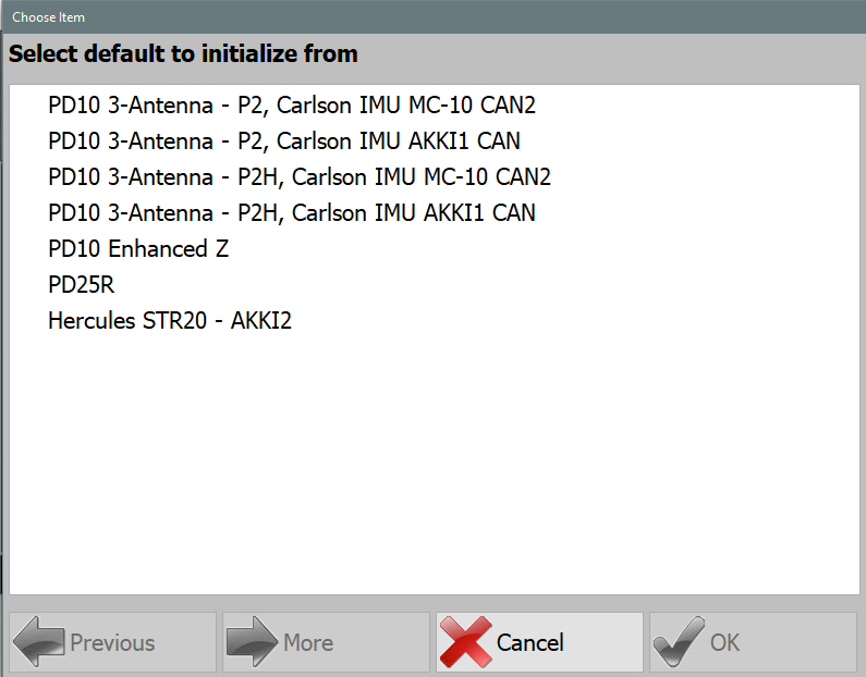
- Initialize PD Settings: Select defaults from a list of common configuration.
- Configure Vehicle: Set up and adjust pile driver settings.
- Configure Rover: Calibrate and optimize GPS settings for accuracy.
- Vermeer Interface Settings: Set up communication with the Vermeer interface.
- Configure Projects: Manage project-specific configurations.
- Settings Report: Produce a PDF report containing the current settings.
Initialize PD Settings
Configure Vehicle
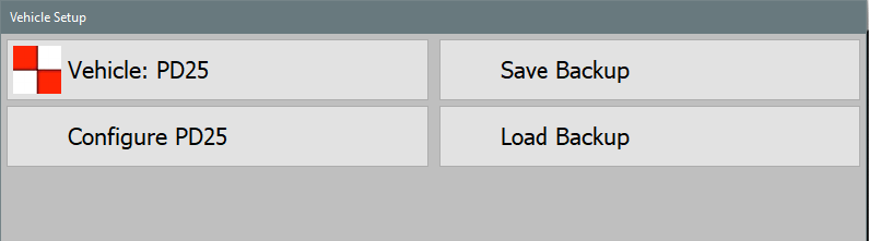
Vehicle
- Pile Driver: Single receiver setup with positioning and heading from two antennas on the mast with a distance laser targeting the hammer, inclinometer on the mast.
- PD10 Hammer GNSS: Vermeer PD10 dual receiver setup with heading from two non-RTK antennas on the mast, hammer position and elevation calculated from antenna mounted on the hammer, inclinometer on the mast.
- PD10 Enhanced Z: Vermeer PD10 dual receiver setup with heading from two RTK antennas on the mast, XY hammer position from the hammer antenna, Z hammer position from the primary heading antenna and a distance laser targeting the hammer, inclinometer on the mast.
- PD5 Hammer GNSS: Vermeer PD5 dual receiver setup with heading from two non-RTK antennas on the mast, hammer position and elevation calculated from antenna mounted on the hammer, inclinometer on the mast.
- Hercules Pile Driver: Hercules STR20 or STR18 setup with positioning and heading from two RTK antennas on the mast, sensor data from Hercules CAN (J1939 or CANOpen).
- Crane Piler: Cable Crane with a mast tower attached, positioning and heading of the mast and hammer from two RTK antennas mounted on the mast with a distance laser targeting the hammer, inclinometer on the mast. Additional positioning and orientation of the crane available via additional RTK antennas and inclinometers.
- Mastless Crane Piler: Cable Crane with vibratory hammer at the end of the cable, positioning and heading of the hammer from two RTK antennas mounted on the hammer. Additional positioning and orientation of the crane available via additional RTK antennas and inclinometers.
- Ojjo Truss Driver: Ojjo Truss Driver with two RTK antennas mounted on the mast, inclinometer on the mast.
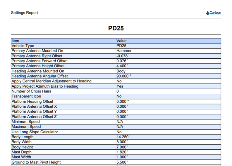
- PD25: Vermeer PD25 dual receiver setup with heading from two RTK antennas mounted on the engine compartment, single RTK antenna on the hammer, sensor data from Vermeer CAN.
- Orecto Integrated: Orteco pile driver with RTK antenna on the hammer and RTK antenna on the mast, sensor data from Orteco integration.
Configure Vehicle
- The configuration menu is structured as a tree-list on the left, allowing selection of different setting categories.
- Selecting a category opens its specific settings.
Note: This section is intended for qualified installers. If you encounter issues, contact your Carlson representative. This documentation serves as a reference only.
Note: This section contains general information about the Configure Vehicle menu. For individual vehicle type instructions refer to the installation manual for each vehicle.
Geometry
This section contains information about the measurements of the pile driver.
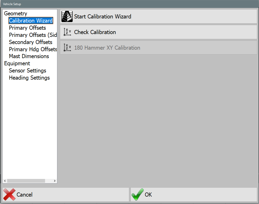
Calibration Wizard
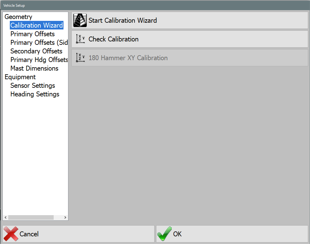
Start Calibration Wizard
This will walk you through the steps of configuring the machine. This should only be done while following the Motium_MC-8_10_PD10 Install-Calibration Manual. If you do not have access to this manual contact your Carlson representative.
- Chassis Dimensions: These dimensions are for icon scaling. See visual for further clarification.
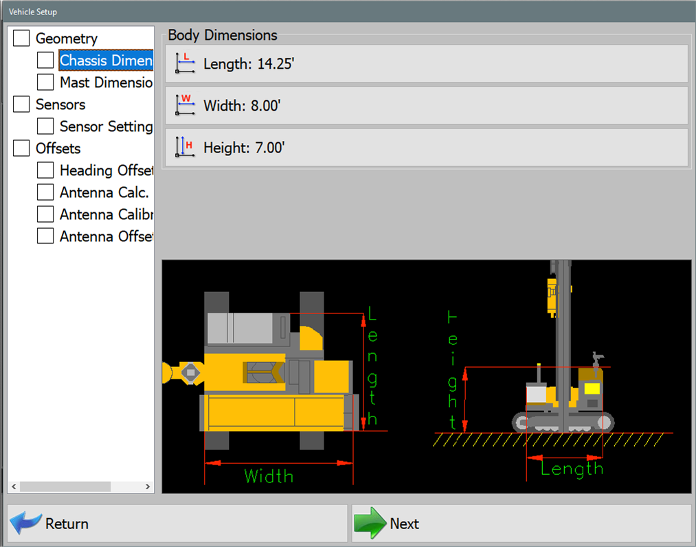
Chassis Dimensions - Length: Length of the machine tracks.
- Width: Width of the machine from outside of track to outside of track.
- Height: Distance from ground to top of cab.
- Mast Dimensions: These dimensions are for icon scaling.
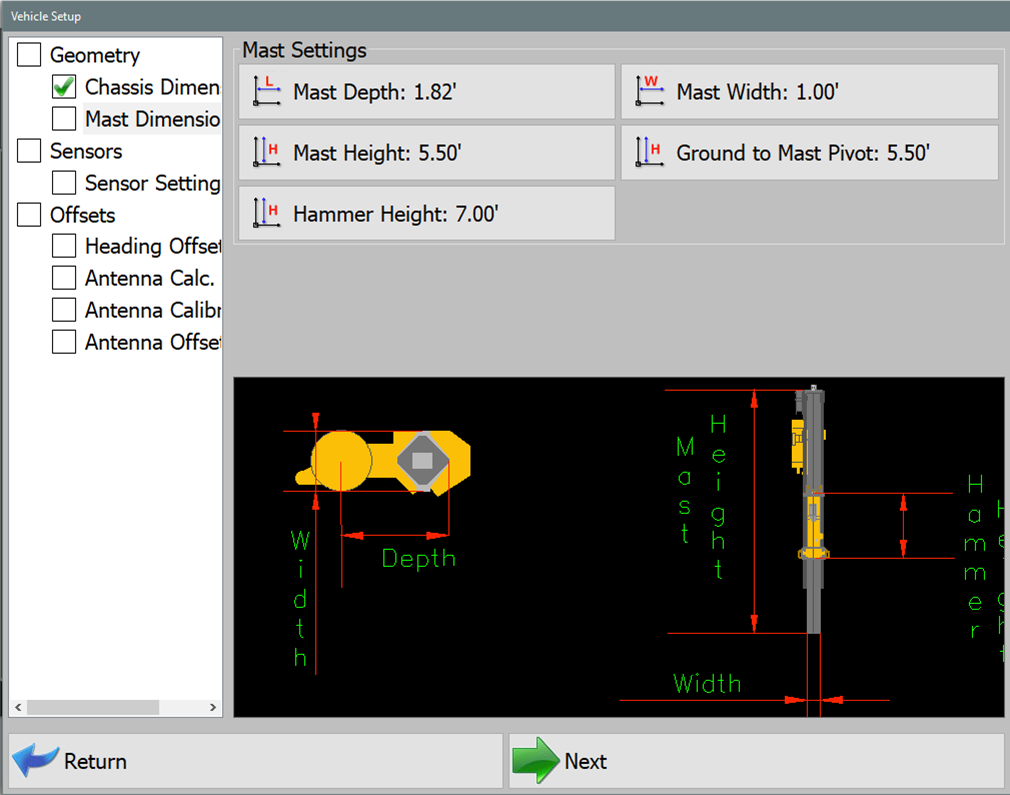
Mast Dimensions - Mast Depth: Length of mast depth.
- Mast Width: Width of mast.
- Ground to Mast Pivot: Distance from ground to Mast pivot point (pivot for tilting mast for transport).
- Sensor Settings: Sensor type selection, mounting location (placement), and orientation setup. Includes slope sensors and distance lasers. Laser Distance sensors will be CAN based (located in Configure Sensors menu) or Serial (COM) based hardware.
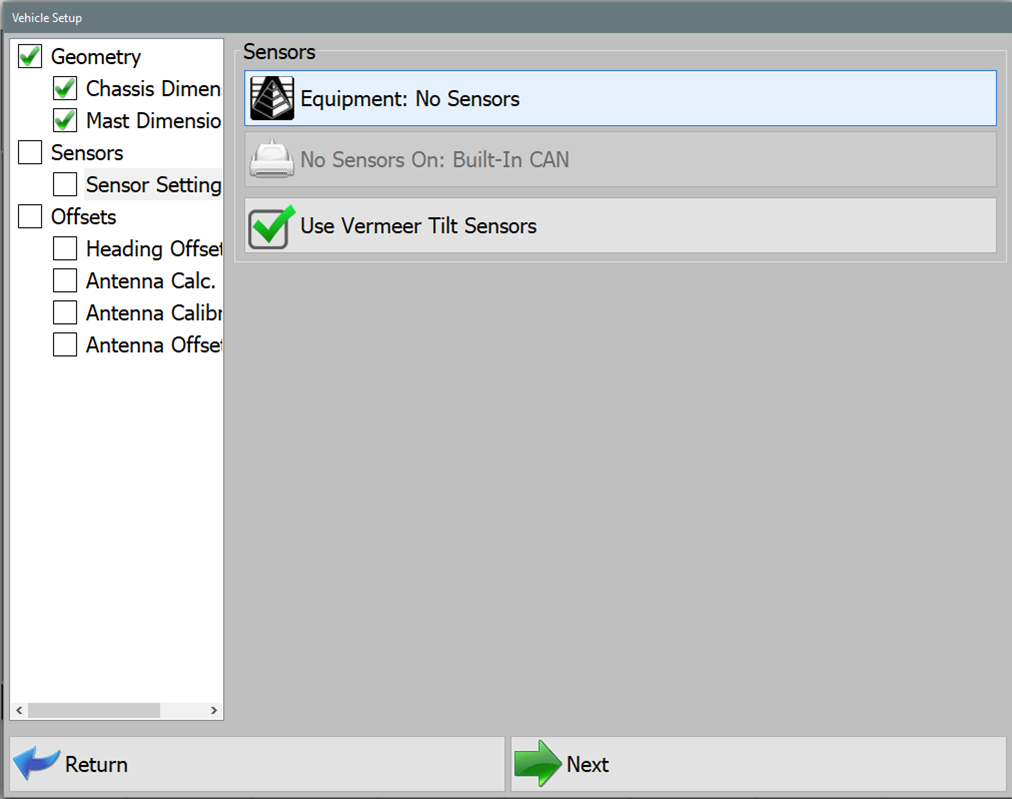
Sensor Settings 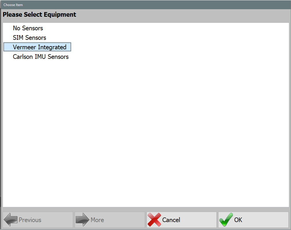
Vermeer Integrated - Vermeer Integrated: For further information, refer to Vermeer Interface Settings later in this document.
- Carlson IMU Sensors: Continue with material that follows.
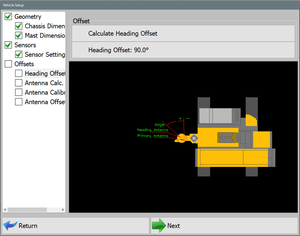
- Heading Offset: Calculate Heading Offset using string line or laser level to square machine mast with 2 collected GPS rover coordinates.
Heading Offset 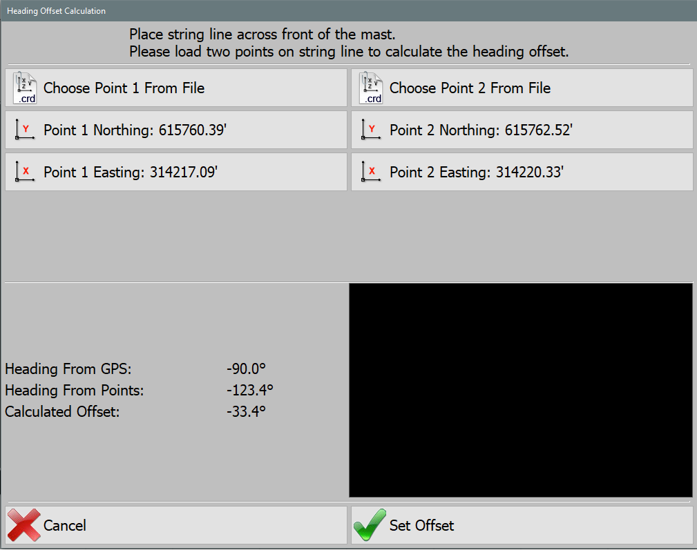
Heading Offset Calculation
Antenna Offset Calibration
Note: Survey rover is required to calibrate Hammer Antenna Height. Using a survey rover, place the survey rover on Top/Center on the installed pile. Remove any Rod Height values in the data collection software and set to 0.0. Set survey rover antenna to read from base of receiver. Record the NEZ (Northing, Easting, Elevation) at top/center of pile using the survey rover.
Note: Hammer Antenna is machined to locate directly above the center of the striker plate. Right & Forward Offset should be 0.0 or close to 0.0 if the hammer and mast are parallel with one another. As hammer bushings, pucks, and shims show wear, the Right/Forward offsets may show a slight offset in the calculated values.
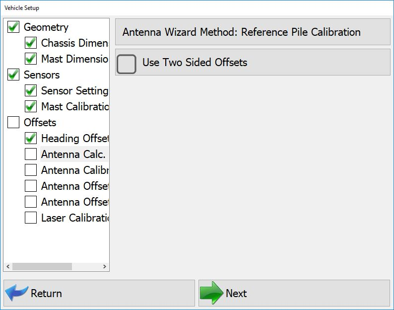
- Use Two Sided Offsets: Two sided offsets may only be used if running C Channel piles, if seeing discrepancies in row to row accuracies, or Custom Guides that do not center piles beneath the center of the striker plate. If Two Sided Calibration Method is selected, once you have calculated Side A antenna offsets, you will be prompted to move to the opposite side of the pile (180°) to calculate and record Side B offsets.
Antenna Calculations - Two Sided - Single Side Calibration: Leave Use Two Sided Offsets unchecked to select single side calibration. This will remove Side A & Side B from Calibration Wizard.
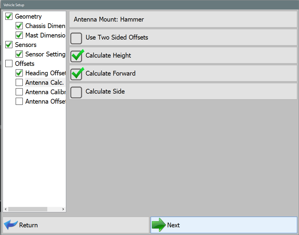
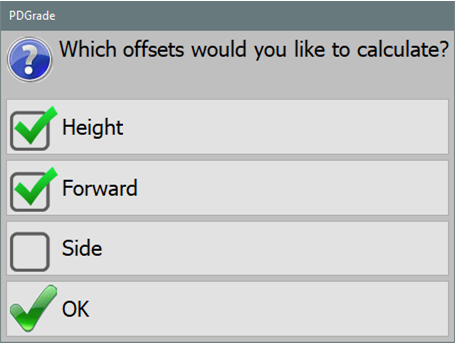
Antenna Calculations - Single Side - Calculate Height: Select this option to calculate a vertical offset distance between Hammer Striker Plate and Hammer GNSS Antenna.
- Calculate Forward: Select this option to calculate a Forward/Back horizontal offset distance between center of Hammer Striker Plate and Hammer GNSS Antenna.
- Calculate Side: Select this option to calculate a Right/Left horizontal offset distance between center of Hammer Striker Plate and Hammer GNSS Antenna.
- Once you have selected offset options to calculate, press NEXT.
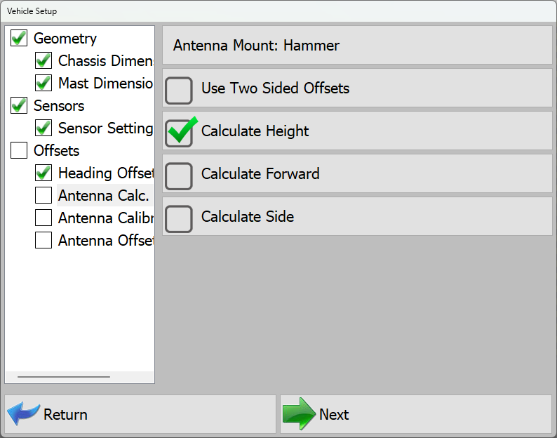
Calculate Height Only - If Calculate Height is the only selected option, the software will prompt you to lower Float the hammer on top of the calibration pile.
Float Alert - With Calculate Height only selected, the software will then prompt you to enter only the surveyed elevation of the pile.
- Enter the surveyed elevation of the pile and press Read GPS and Calculate Offsets.
Elevation to Read - Then press Next.
- Offset calculated and populated will only be the Hammer Antenna Height.
Calculated Offset - Press OK.
Calibration is Complete.
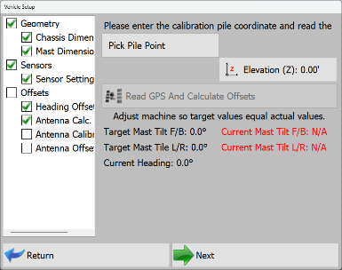
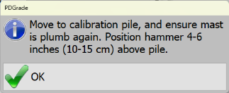
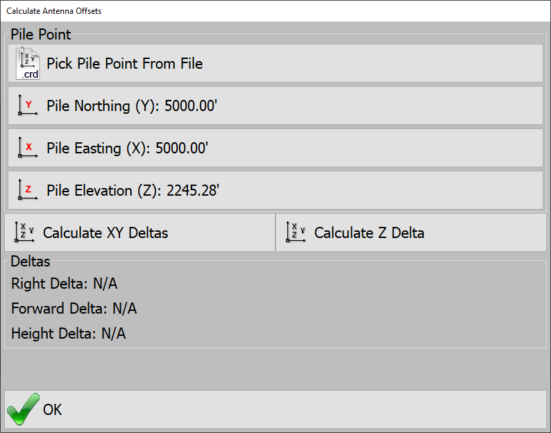
If Calculate Height, Forward, and Side are selected options, the software will first prompt you to center the hammer over the calibration pile and position 4"-6" over the pile. If the weight of the hammer is on the pile, this will cause hammer antenna horizontal offset errors during the calibration.
- Level Mast to within ±0.1°.
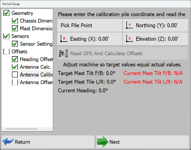
Float Alert - Software will prompt you to enter N,E,Z of the surveyed pile.
- Enter the surveyed N,E,Z and press Read GPS and Calculate Offsets.
Antenna Calculations - Height, Forward, Side - Once the horizontal offset is calculated, the software will then prompt you to lower Float the hammer onto the pile.

Antenna Offsets - Press OK.
Calibration is Complete.
Check Calibration
Check Calibration XYZ (Easting, Northing, and Elevation)
- When checking XYZ, survey the center of the pile that will be used to check calibration.
Check Offsets - Enter surveyed N,E,Z from the Center of the pile.
- Press Calculate XY Deltas.
- The software will prompt you.
- position the hammer centered 4"-6" above the pile.
- Level Mast to within ±0.1°.
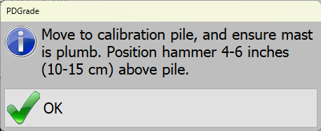
Float Alert - Hammer should NOT be loaded onto the pile when checking XY. If the weight of the hammer is on the pile, this will cause hammer antenna horizontal offset errors during the calibration check.
The deviation between surveyed point and Hammer position will be calculated in the Right and Forward Delta values.
Check Calibration Z (Elevation)
- When checking Z, survey the center of the pile that will be used to check calibration.
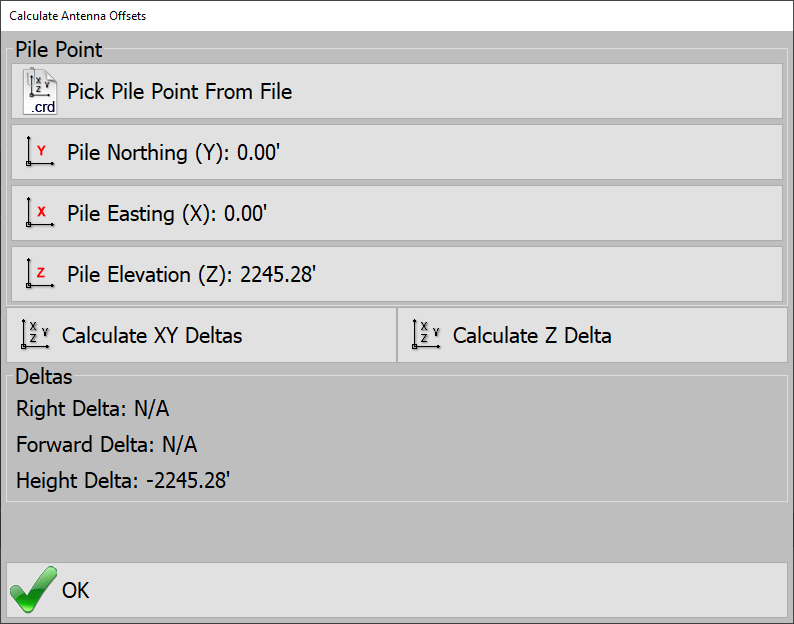
Check Z (Elevation) - Enter surveyed Z from the Center of the pile.
- Press Calculate Z Delta.
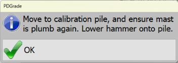
- The software will prompt you to lower Float the hammer on top of the calibration pile. Ensure the hammer is loaded onto the pile.
- Level Mast to within ±0.1°.
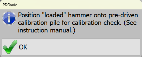
Float Alert - Press OK.
The deviation between surveyed point and Hammer position will be calculated in the Height Delta value.
Primary Offsets
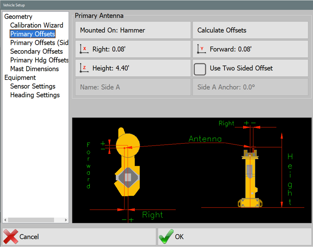
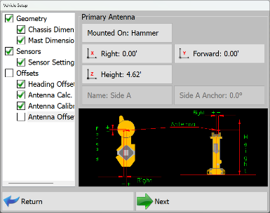
Enter the Forward, Right, and Height of the primary GPS antenna.
- Mounted On: For PD Grade, the Primary GPS will always be mounted on the Mast.
- Forward: The distance that the antenna is in from or back from the hammer. Back is represented by a negative (see image).
- Right: The distance that the antenna is placed to the right of the center of the machine. If the antenna is to the left of the center of the machine then the Right will be negative. See Image.
- Height: The distance that the antenna is above the ground.
- Use Two Sided Offset: Two sided offsets may only be used if running C Channel piles, if seeing discrepancies in row to row accuracies, or Custom Guides that do not center piles beneath the center of the striker plate. If Two Sided Calibration Method is selected, once you have calculated Side A antenna offsets, you will be prompted to move to the opposite side of the pile (180°) to calculate and record Side B Offsets.
Calculate Offsets
In this menu you can choose a set point and position the hammer at that point and then calculate the Position Offset from the GPS receiver to the center of Hammer.
Note: This menu is part of the wizard and should only be performed by a qualified technician.
Enter Northing, Easting, and Elevation from the recorded top of Calibration Pile or Choose Point from File.
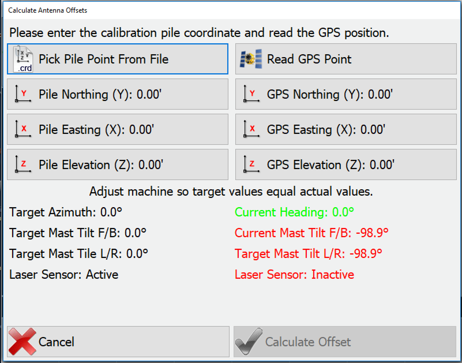
- Then press Read GPS Point.
- This will fill in the GPS Y, X, and Z.
- Then press Calculate Offset.
PD Grade will then fill in the primary offsets for you.
Primary Hdg Offset
Note: This menu is part of the wizard and should only be performed by a qualified technician.
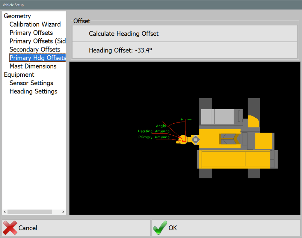
- Press Calculate Heading Offset.
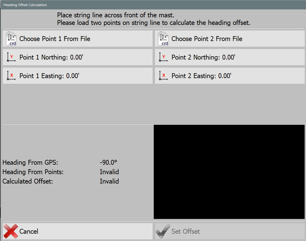
Heading Offset Calculations - Enter Northing and Easting from recorded Point 1 or Choose Point from File (the coordinate file can be loaded as csv format if available).
- Enter Northing and Easting from recorded Point 2 or Choose Point from File.
- Press Set Offset.
PD Grade will then fill in the heading offset.
Sensor Offsets
This section calculates the laser sensor.
Note: This menu is part of the wizard and should only be performed by a qualified technician.
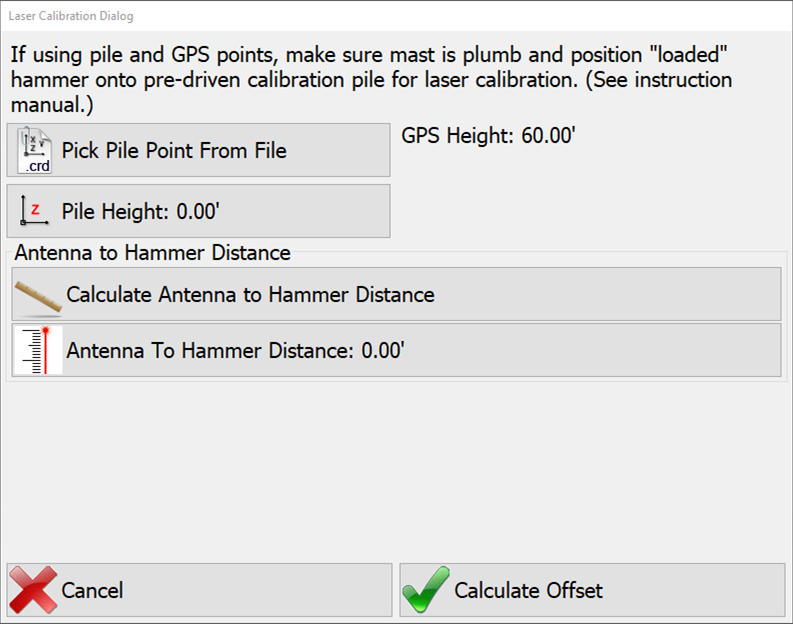
- Press Calculate Sensor Offset.
- Enter the Pile Height or choose it from a points file.
- Press Calculate Antenna to Hammer Distance.
PD Grade will then fill in the sensor offset.
Mast Dimensions
These dimensions are for icon scaling. See visual for further clarification.
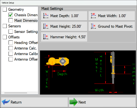
- Mast Depth: Distance from the mast to the outside of the hammer.
- Mast Width: width of the hammer on the mast.
- Ground to Mast Pivot: Distance from the ground to the pivot point on the mast.
Chassis Dimensions
These dimensions are for icon scaling. See visual for further clarification.
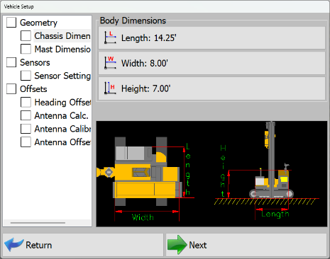
- Length: Length of the machine tracks.
- Width: Width of the machine from outside of track to outside of track.
- Height: Distance from ground to top of cab.
Settings
Crosshair Options
The crosshair feature draws a circle at a radius and lines across the hammer.
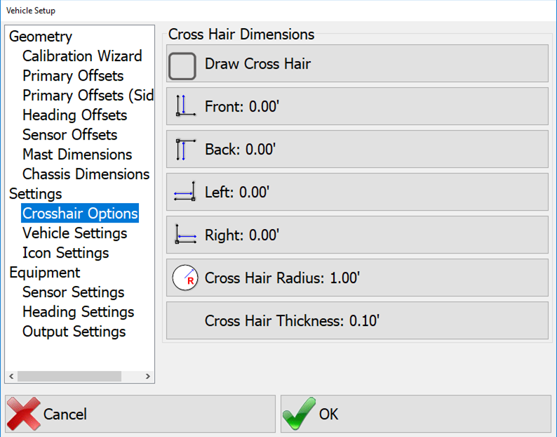
- Draw CrossHair: Turn the crosshair feature on.
- Front, Back, Left, Right: Lines of a specified length across the hammer.
- CrossHair Radius: Radius of circle drawn around the hammer.
Vehicle Settings
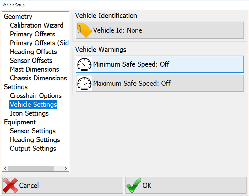
- Vehicle ID: (Deprecated) This is the Heartbeat ID and is no longer used to identify the vehicle in Carlson Command. It can be set if broadcasting to other machines in Heartbeat Settings.
- Minimum Safe Speed: If the vehicle goes below this speed the operator will see an alarm on the main screen.
- Maximum Safe Speed: If the vehicle goes above this speed the operator will see an alarm on the main screen.
Equipment Settings
Icon Settings
This feature allows the user to load custom icons for the vehicle. Select Body Top and Body Side and choose files for each.
Sensors Settings
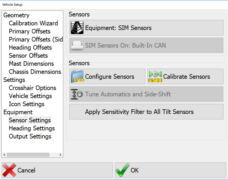
- Equipment: Select the type of sensors that are installed.
- Sensors On: Select the interface (Serial or CAN) to the sensor.
- Configure Sensors: Enter the configuration menu for sensors. (See below).
- Calibrate Sensors: Enter the sensor calibration menu (See below).
- Apply Sensitivity Filters to All Tilt Sensors: In the calibration menu there are filter levels that can be set to individual sensors. If you wish to set all of the sensors to the same filter level you can use this feature. Press the button and set the level, and then select Apply to All.
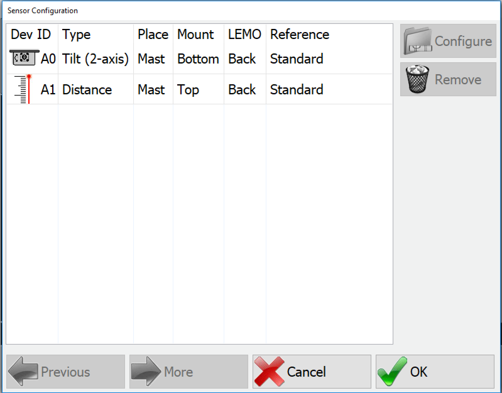
Configure Sensors
Note: This menu is part of the wizard and should only be performed by a qualified technician.
To configure a sensor select, it from the list and then press the Configure button.
Note: For full details pertaining to how to mount and calibrate sensors, see the Motium_MC-8_10_PD10 Install-Calibration Manual.
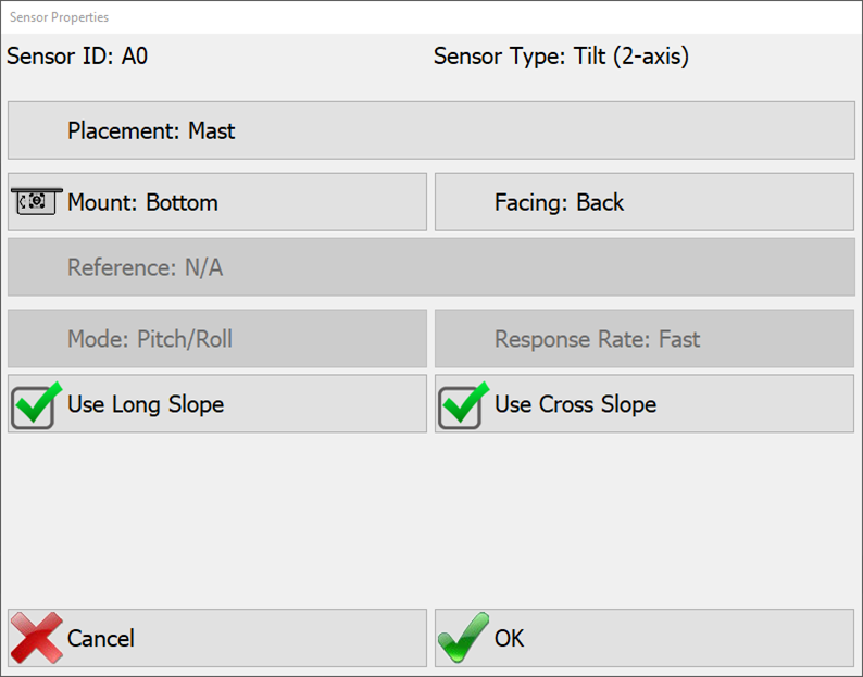
- Placement: Where the sensor is mounted. Options:
- Mast (Display only will only be used for display and not for calculating piles)
- None
- Mount: How the sensor is oriented. Options:
- Top
- Bottom
(see image, for axial sensors only)
- LEMO: This is the direction that the cable is facing with respect to looking forward in the vehicle (driver's perspective).
- Use Long Slope: If unchecked, the long slope value calculated by the sensor will be ignored by the software.
- Use Cross Slope: If unchecked, the cross slope value calculated by the sensor will be ignored by the software.
Calibrate Sensors
Note: This menu is part of the wizard and should only be performed by a qualified technician.
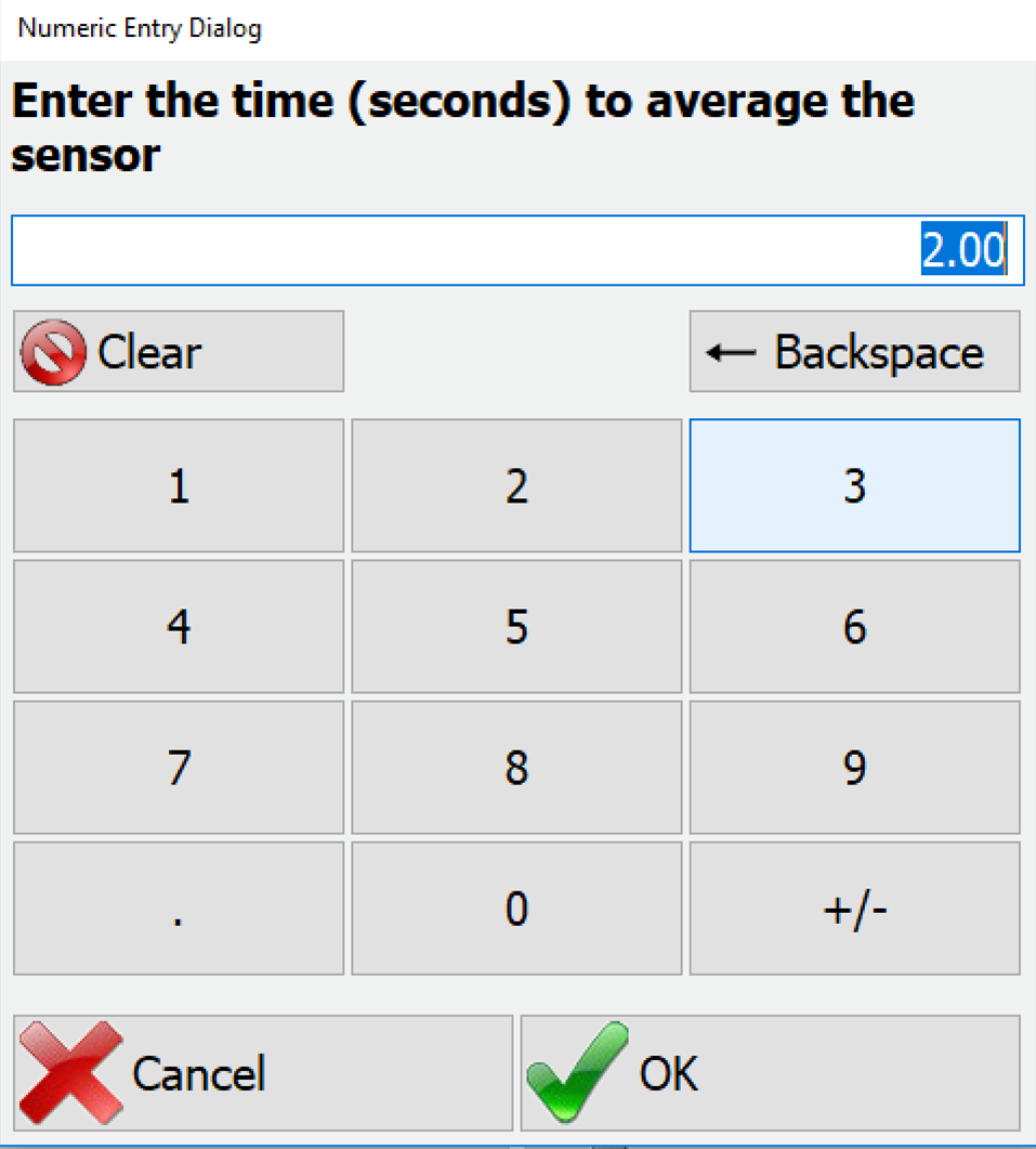
When you first enter the calibration menu you will be asked how long to average the sensors. This is how long the reading will be taken for calibration. Longer times will have better results but the default value of 2 seconds is adequate for most operations.
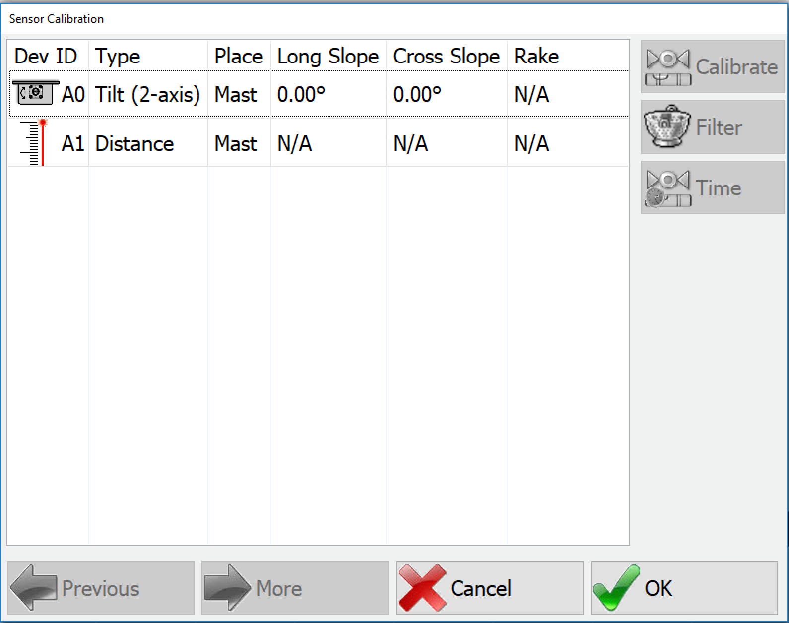
Select the sensor on the left and press calibrate.
- Tilt: You will be asked to enter the desired Mast cross slope angle in degrees, and then the desired Mast long slope angle. Once entered the program will calibrate the sensors from the entered parameters.
- Laser: You will be prompted to position the hammer on a stable surface. Then measure and enter the distance from the GPS antenna to the bottom of the hammer. The program will then calculate the offset and prompt you to accept the offset.
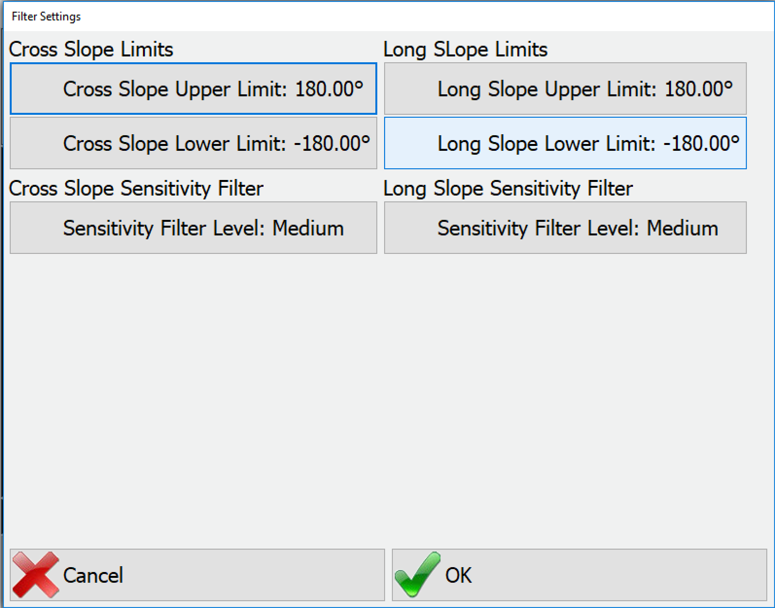
Tilt Filters
Tilt sensors can be filtered to reduce noise in the signal. Select the tilt sensor and press Filter.
The filters are separated into Cross and Long slope limits but function the same way.
- Upper and Lower Limits: In degrees the maximum and minimum values the program will use for slope.
- Sensitivity Filter: This uses a weighted moving average to reduce noise in the sensor signal. The levels are:
- High
- Medium
- Low
All tilt sensors are set to medium by default. Adjustments of these filters depends on the type of work performed and should be evaluated on a site-by-site basis.
Heading Settings
If using a second GPS receiver for heading (versus using a single receiver that provides heading with dual antennas), configure it here using the same method discussed in the next section (Configure Rover). Alternatively, a Reverse Sensor can be used instead of GPS Heading. If so, select the port that the reverse sensor is on.
Configure Rover
After all equipment installation is complete, connect to the AKKI1 GNSS Receiver and Setup the RTK (Real Time Kinematics).
- Select the AKKI1 Single GNSS Receiver under the Instrument Selection. The default Rover will be GPS Simulation. The AKKI1 Single will be located under Instrument Selection → Carlson → AKKI1:
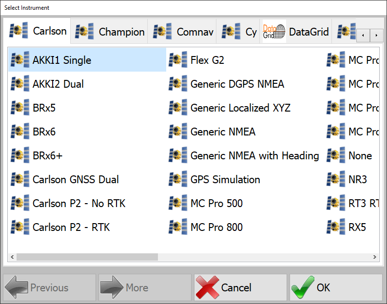
Select GNSS Receiver - Enter the AKKI1 communication settings as follows:
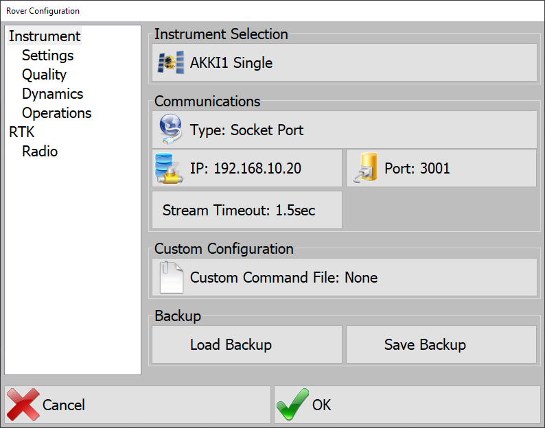
Set Communication Settings - Type: Socket Port
- IP:
192.168.10.20 - Port:
3001
This is the communication between the AKKI1 and MC-8/10.
Settings
Select and enter the options for the AKKI1 GNSS receiver.
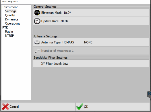
- Elevation Mask: 10°
- Update Rate: 20 Hz
- Antenna Type: HEMA45
- Click to Highlight: Hemisphere GPS
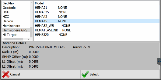
Select Antenna - Next, Click to Highlight: HEMA45
- Press Select
- Click to Highlight: Hemisphere - HEMA45
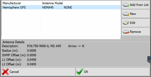
Select Hemisphere - Press OK
- Click to Highlight: Hemisphere GPS
- Number of Antennas: 1
- XY Filter Level: Medium
Quality
The default Quality Options are set for the AKKI1 receiver. There is no need to change these settings.
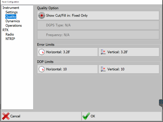
- Show Cut/Fill in: Fixed
- Error Limits:
- Horizontal: 1m (3.28FT)
- Vertical: 1m (3.28FT)
- DOP Limits:
- Horizontal: 10
- Vertical: 10
Dynamics
Some dynamic settings will be grayed out depending on the manufacturer of the GNSS receiver.
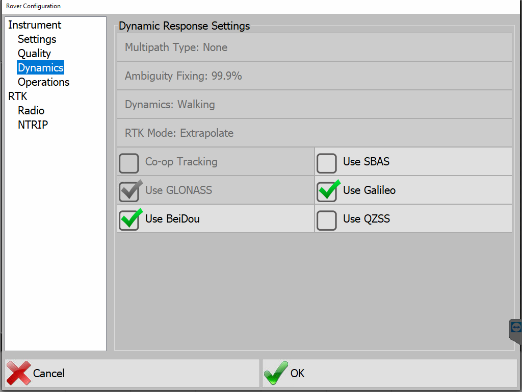
For the AKKI1 receiver, you will want to ensure that all GNSS constellations that are wished to be used are checked. The AKKI1 GNSS receiver will NOT use any constellations that are unchecked. Carlson highly recommends turning ON Galileo & BeiDou.
- GPS: United States Satellites
- Glonass: Russian Satellites
- Galileo: European Satellites
- BeiDou: China Satellites
Operations
The Operations menu is used to send specific commands to reset, enable, or disable certain features of the receiver.
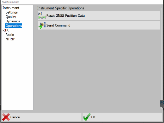
- Reset GNSS Position Data: This clears the receiver's NVRAM and previous Satellite data. Recommended when setting up the system in a new location and/or jobsite.
- Send Command: Opens a manually input bar to send specific manufacturer commands to the receiver.
RTK
The following information will list two ways to connect to the local base station.
Option 1 - UHF Radio
RTK using AKKI1 Internal UHF Radio
The AKKI1 has an Internal Satel UHF Radio. This is a situation in which the local base station has a UHF Radio that is transmitting the RTK corrections. The radio setting in the AKKI1 must match that of the local base station.
Enter the following Options:
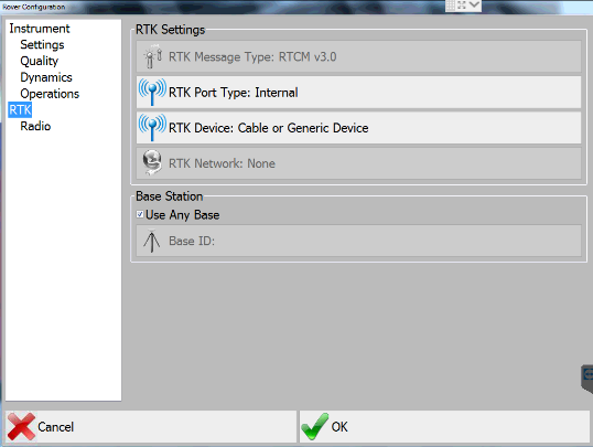
- RTK Port Type: Internal
- RTK Device: Internal Radio
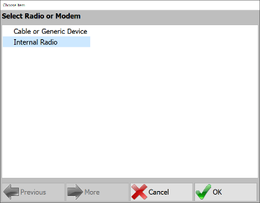
Select Internal Radio - Base Station: Unless the base has a specific ID, leave the default box checked Use Any Base.
- RTK Radio Settings: Enter the following settings to connect to the Internal Radio of the AKKI1 GNSS Receiver.
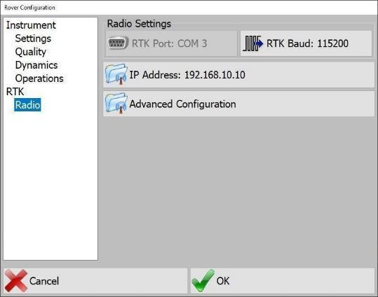
Select Internal Radio - RTK Baud: 115200
- IP Address:
192.168.10.10
Grade will connect to the internal radio of the AKKI1 and retrieve the current settings. You will then change all radio settings to match that of the local base station.
- Set the parameters to match the settings being broadcasted by the site installed GNSS Base Station.
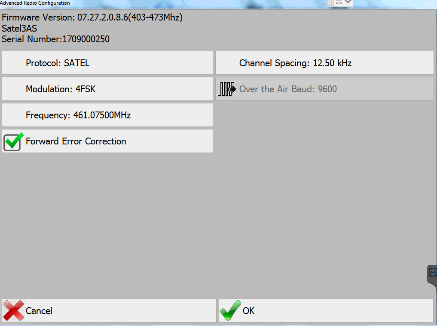
Radio Parameters and FirmWare Version - Protocol ____________
- Channel Spacing ____________
- Modulation ____________
- Over Air Baud (If applicable)
- Frequency ____________
- Forward Error Correction ON or OFF
RTK corrections will need to be ported from the AKKI1 to the AKKI2. The AKKI2 will receive RTK corrections from the base station through the AKKI1 receiver. The RTK porting feature resolves the need for a 2nd UHF radio to be installed on the PD10.
- Enable RTK Correction Forwarding to port RTK corrections to an IP Address and Destination Port.
- Enter the following values:
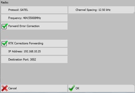
RTK Correction Forwarding - IP Address:
192.168.10.25 - Destination Port:
3002
- IP Address:
- Select OK
- Select OK to exit Rover Configuration page to return to the main working screen.
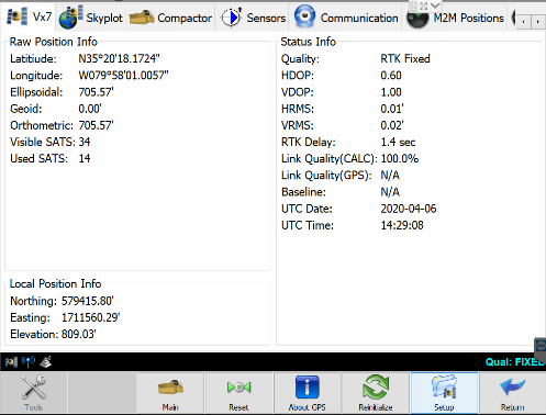
Go to Tools → Show Monitor Screen to check the quality of the RTK.
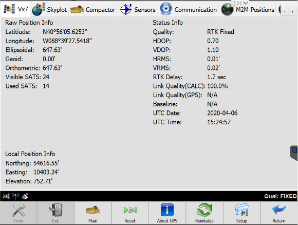
Note: RTK Fixed indicates that RTK has reached the highest quality and is receiving data.
If you don't get a Fixed solution, troubleshooting is necessary. Ensure all settings are correct.
Option 2 - NTRIP
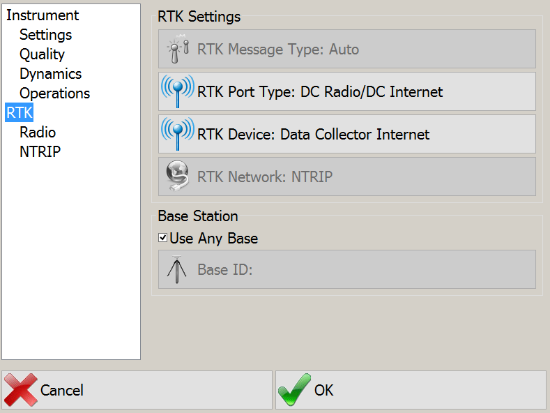
- RTK Message Type: You can manually select and match the message type or select Auto.
Note: Grade will automatically recognize the message type when this option is selected.
- RTK Port Type: This is the port in which the AKKI1 will receive base station corrections. For NTRIP, use DC Radio/ DC Internet.
- RTK Device: Select the device in which the base station will be contacted. In this case we will use Data Collector Internet.
- RTK Network: NTRIP
- Base Station: Unless the base has a specific ID, leave the default box checked Use Any Base.
Note: RTK Radio Settings: All options will be blocked and unable to be changed except Output Port.
- Change the Output Port to Data
- NTRIP Selection: Select NTRIP Caster
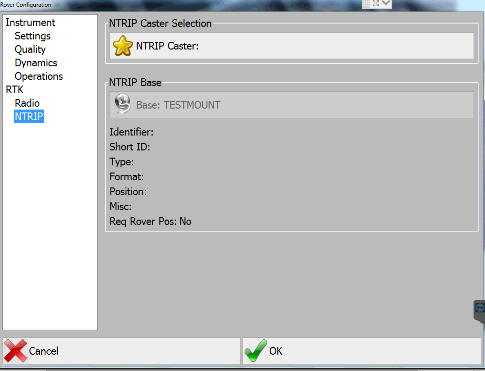
Select NTRIP - Select Add New Entry
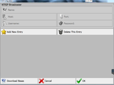
New NTRIP Broadcaster
Entering New Caster Name, Address and Mount Point
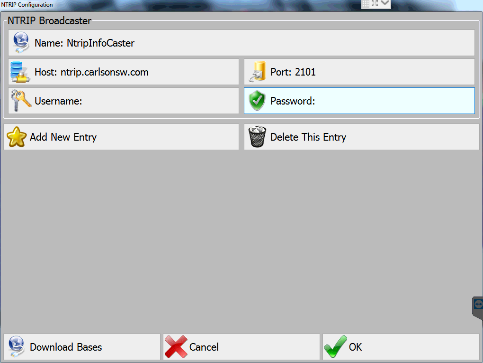
- Select Name and Add Name of the NTRIP Host.
- Host → Enter Host Address: This can be a Site Web address name or the Server IP address.
- Port → Port Number
- Enter Username and Password
- Select Download Bases. Grade will connect to the host and download all currently available bases.
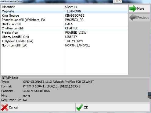
Select NTRIP Base - Select the Mount Point → OK.
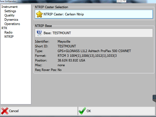
Base Information The NTRIP connection is complete.
- Select OK to connect.
Navigate to Tools → Show Monitor Screen to check the quality of the RTK.
Vermeer Interface Settings
These settings connect to the Vermeer CAN data through the AKKI Receiver.
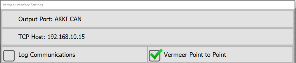
- Set the Output Port to AKKI CAN
- Set TCP Host to
192.168.10.15 - Log Communications: Stores a CAN log to
C:\Data\Diagnostics\$VermeerCANdebug1.log
For more details refer to the Vermeer_PD25R_HammerGNSS_InstallManual_2025.
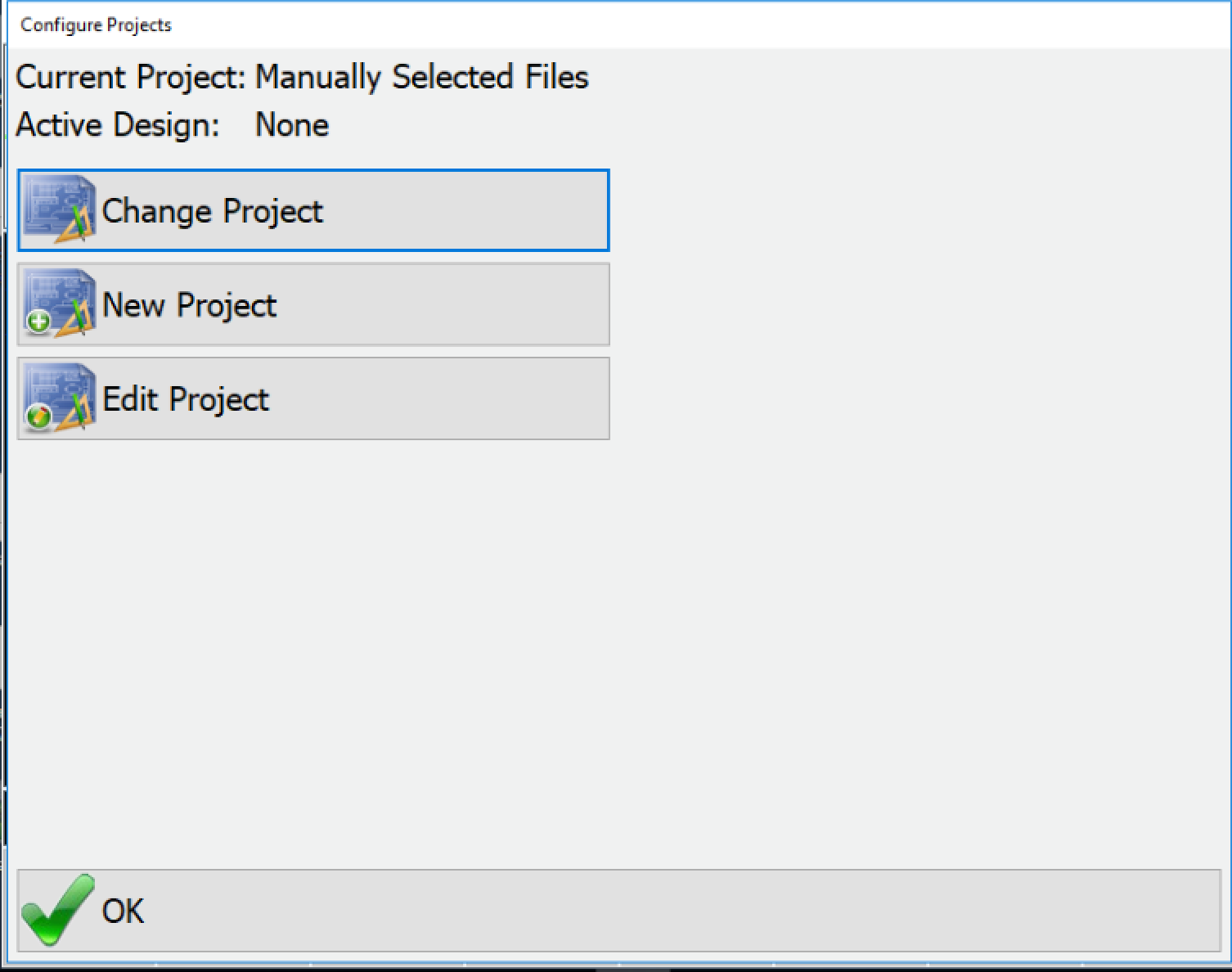
Configure Projects
A project is a collection of files such as:
- plan view
- design DTM
- localization
- optional files such as: centerline and coordinate files
Change Project
This allows the user to activate to an alternate project.
New Project
New Project allows the user to create a project from scratch. Press New Project to give the Project a name.
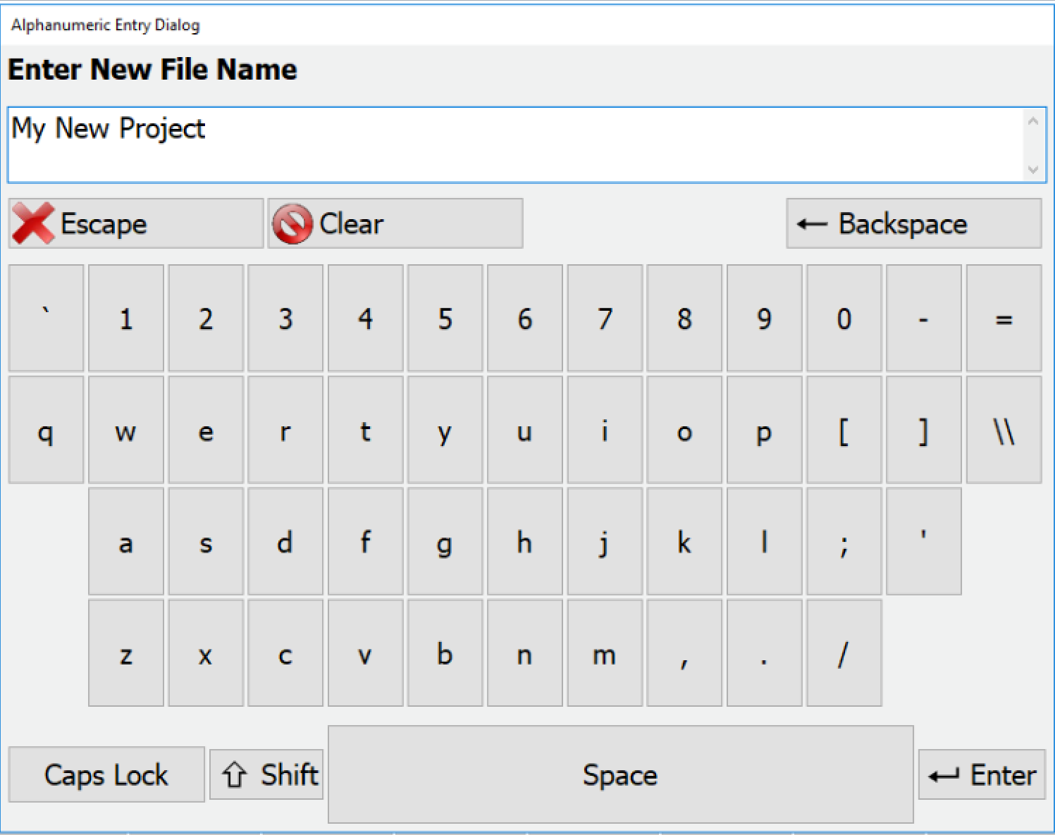
This name will be the name of the .PRJ file created for this project. A .PRJ file is a configuration file for the project. It does not contain the individual files needed for the project to function. If you choose to export the project, a .PRZ (Project ZIP) will be created containing the .PRJ and all associated files.
Next you will get a menu with sub-sections in a list on the right, and entries and options on the right.
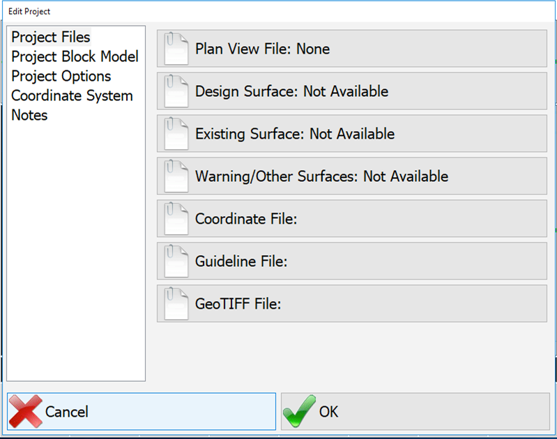
Project Files
The actual plan view, surface, coordinate and other files that will be a part of the project
Plan View File:
PD Grade will read DWG and DXF files as the plan view file directly. It will also use PLN files created in Carlson Software office products such as Civil Suite™ (SurvCadd), Takeoff, Carlson Survey, Leica Site Manager and TopSite. Whatever colors appear on the source file will appear on the file within PD Grade. However, bold linework will be presented at standard width. Text may appear on the screen in PD Grade. If a DWG file is used, only the polyline elements on the file will be captured by PD Grade. It is recommended that files be simplified before loading into PD Grade.
To select a file or files, click the Plan View File: button on the right. This will take you to a selection screen. Pressing add will take you to the file browser screen where you can select already existing files from the hard drive or navigate to a USB drive to select from there. You may add as many plan view files as desired. To remove them from the list, select them and press Delete. Press OK to accept the selection.
Design Surface, Existing Surface, Warning/Other Surfaces:
PD Grade does not require any surfaces. The UOA will make these functions unavailable in PD Grade.
Project Options
- Project Description: This is a user defined description. It appears on the status bar of the main page and is used to differentiate between different areas.
- Units: U.S. Survey Feet (0.3048006096 m), International Feet (0.3048 m), Meters (International System of Units)
- Vertical Offset: Not used in PD Grade
Coordinate System
This tab is where the installer will upload the localization file and choose a projection. After a localization file and projection has been selected, there will be no more need to enter this dialogue unless the equipment is moved to a new site.
- Projection: A projection is any method for representing a sphere (or any three dimensional object) onto a plane. Projections can be global such as UTM or local State Plane such as United States/Texas/(North). Click on Projection and choose the correct coordinate plane for the job site.
Note: New projects will automatically use the last projection selected.
- Projection Options: Enter a Geoid file, transformation files, or anything else applicable to the projection.
- Localization File: Upload a localization file in this dialogue or create one using the following instructions.
- Localization Editor: This allows an advanced user to manipulate the localization file for the project. See details below.
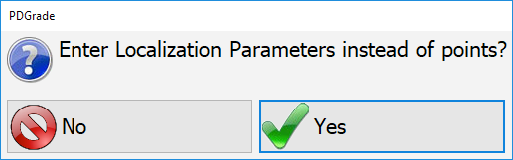
Localization Editor
When you select the localization editor it will give you the option to edit the Parameters or the Points. Choose Yes to edit the parameters, and No to edit the points.
For Parameters, you will be able to edit:
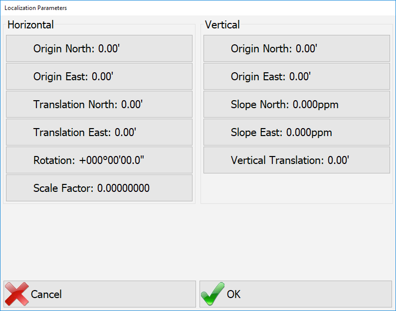
| Horizontal | Vertical |
|---|---|
|
|
The localization editor has two tabs:
- Local Coordinates
- Raw Coordinates
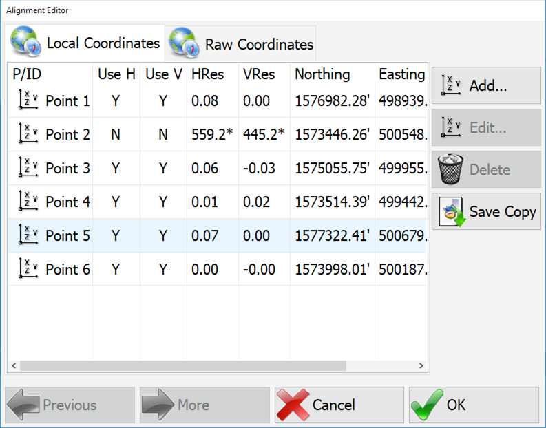
Press Add… to add a new point to the localization. You will be prompted to enter a local coordinate, or select one from a points file (.CRD). Once you have a local coordinate entered, you will be prompted to collect Raw coordinates from the GPS. You can also Edit and Delete points from the list. You can also select Y or N for each point to decide whether or not to use it in the solution. Press Save Copy to save the localization to a file (.LOC).
Note: New localizations are created with Grade Supervisor, SurvCE/PC, or Topcon pocket 3D (gc3).
Edit Project
Edit project allows you to select an existing project and open it for editing. For a description of the menu see New Project above.
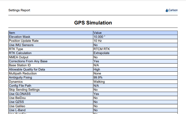
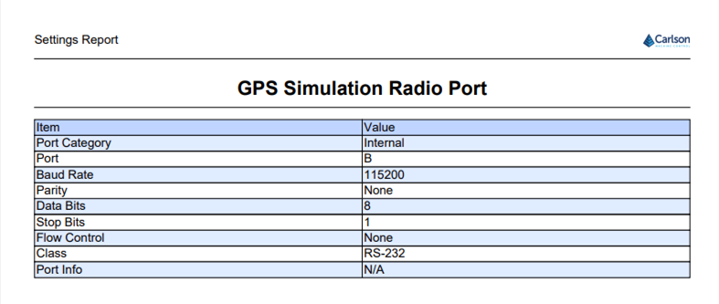
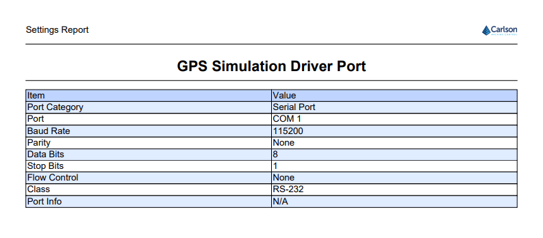
Settings Report
The settings report outputs a snapshot of the major settings after configuration of the system is complete. These can be used for auditing a system setup in the future.

Select the settings to include in the report.
- GPS Settings: Settings from Configure Rover
- Sensor Settings: Settings from Configure Sensors
- Vehicle Settings: Settings from Configure Vehicle
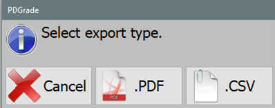
Choose output type for the report
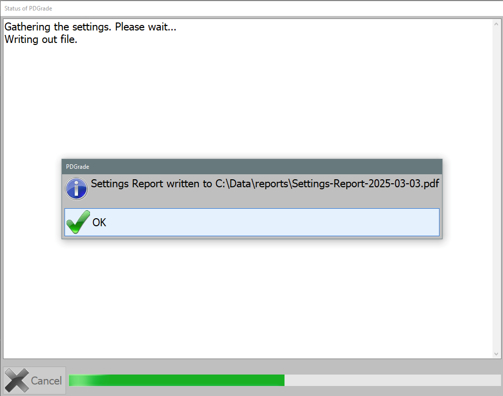
The report is saved in C:\Data\reports with the current date.
Example Output: