This routine will automatically calculate hammer antenna offsets referencing the position of the hammer against a surveyed coordinate.
Note: A survey rover is required to calibrate the Hammer Antenna Height.
Note: It is suggested to use the (or a) Calibration Pile to perform the calibration.
More Information
- Using a survey rover, place the survey rover on Top/Center on the installed pile.
- Remove any Rod Height values in the data collection software and set to 0.
- Set the survey rover antenna to read from base of receiver.
- Record the NEZ at top/center of pile using the survey rover.
Calculate Antenna Offsets
- Navigate to Tools → Calculate Antenna Offsets:
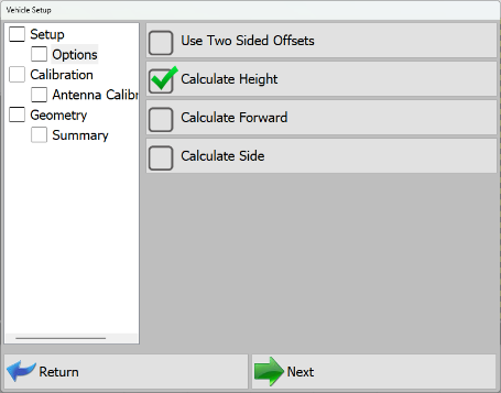
Vehicle Setup - Antenna Calibration - Indicate the desired calibration technique(s):
- Use Two Sided Offsets: Two Sided Offsets may only be used when:
- running C Channel piles, or,
- discrepancies in row to row accuracies, or,
- using Custom Guides that do not center piles beneath the center of the striker plate.
Note: Once you have calculated the Side A antenna offsets, you will be prompted to move to the opposite side of the pile (180°) to calculate and record the Side B offsets.
- Calculate Height: Select this option to calculate a vertical offset distance between the Hammer Striker Plate and the Hammer GNSS Antenna.
- Calculate Forward: Select this option to calculate a Forward/Back horizontal offset distance between the center of Hammer Striker Plate and the Hammer GNSS Antenna.
- Calculate Side: Select this option to calculate a Right/Left horizontal offset distance between center of the Hammer Striker Plate and the Hammer GNSS Antenna.
Note: The Hammer Antenna is machined to locate directly above the center of the striker plate. Right and Forward offsets should be essentially 0 if the hammer and mast are parallel with one another.
Note: As hammer bushings, pucks, and shims show wear, the Right/Forward offsets may show a slight offset in the calculated values.
- Use Two Sided Offsets: Two Sided Offsets may only be used when:
- Once you have selected offset options to calculate, tap Next.
- The calibration sequence will vary slightly based on the option(s) selected above:
- Calculate Height-only: The simplest option, the mast is calibrated to a cited pile elevation.
More Information
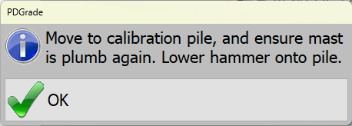
- The software will prompt you to lower ("Float") the hammer on top of the calibration pile.
Calibrate - Height Only - The software will then prompt you to enter only the surveyed elevation of the pile. Enter the surveyed elevation of the pile and press Read GPS and Calculate Offsets.
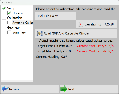
Pile Calibration Elevation - Press Next.
- The Offset is calculated and populated into only the Hammer Antenna Height.
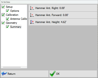
Hammer Antenna Height Summary
- The software will prompt you to lower ("Float") the hammer on top of the calibration pile.
- Calculate Height and Forward and/or and Side: This is a slightly more involved process but can help correct error due to normal wear and tear.
More Information
- The software will first prompt you to center the hammer over the calibration pile and position 4"-6" (10cm - 015cm) over the pile.
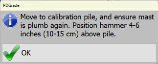
Calibrate - Height and Forward / Side Note: If the weight of the hammer is on the pile, this will cause hammer antenna horizontal offset errors during the calibration.
- Level Mast to within ± 0.1°.
- The software will prompt you to enter N,E,Z of the surveyed pile. Enter the surveyed N,E,Z and press Read GPS and Calculate Offsets.
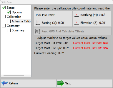
Pile Calibration Coordinates - Once the horizontal offset is calculated, the software will then prompt you to lower ("Float") the hammer onto the pile.
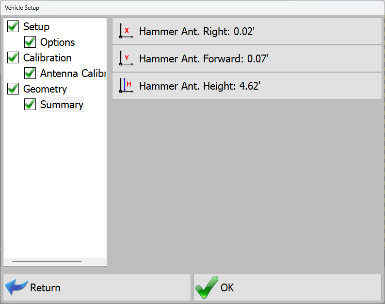
Calculated Right, Forward and Height Offsets
- The software will first prompt you to center the hammer over the calibration pile and position 4"-6" (10cm - 015cm) over the pile.
- Calculate Height-only: The simplest option, the mast is calibrated to a cited pile elevation.
- Press OK.
Calibration is Complete!