 Surface Mass Points Processor
This tool is used to import points from multiple Lidar LAS/LAZ, Grid/Tin surfaces or points files. It contains several useful constraints that can help reduce the number of points extracted from these files to lower the data burden and speed surface operations. The output can be a TinSurface, GridSurface, Points or an exported file of these formats. Another option for extremely large surfaces is a post processor option that creates a special point file, then launches a system tray (taskbar) application that triangulates in the background freeing up the CAD session.
Keyboard Command: SurMasPts
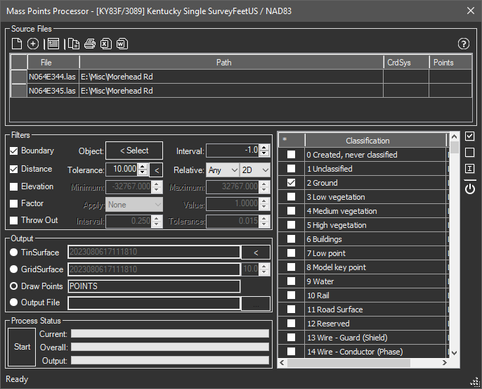
- Source Files: This is the list of source files to be evaluated. Points from these files that pass the constraints are added to the generated surface. If the current file has been assigned a coordinate system, there will be a CrdSys column on the far right. When the selected files are added to the grid, the tool looks for files of the same name (but different extension) in an attempt to auto-detect the coordinate system of the file. In the event it fails to detect it, you can select the row(s) and click the assign system button (third from left) and select one.
You can select files on your local drives or (in certain regions) download the needed Lidar data from an adjacent list. Pull down the list and choose your region from the list (if it exists). Adjacent buttons let you get information about the download source, designate the folder to keep cached copies in, and a button to begin downloading. If you plan to use a boundary object you should select it before beginning the download, otherwise all files in the drawing extents are downloaded.
If your region is not shown in the drop down and you know it has an intelligent index and direct download options, email us through the information found at the Contact DotSoft Technical Support page with the information and we will attempt to add it.
- Filters:
- Boundary: Optional plan boundary limits to the resulting data. You can choose almost any closed linear object to indicate the area of interest. The interval field controls how far apart points are on objects that need it, like circles and polylines with arcs. For fastest processing prepare a polyline with no arcs and leave the field at 0.0.
- Distance: Optional distance point elimination. If a point lies less than the specified distance to either the last point evaluated or any point, it is discarded. Lidar is usually collected in sweeping left/right paths. The last option does not consume any memory and is fairly fast. The "any" option must store the kept points so it consumes memory and as the list of kept points increases, the speed decreases.
Filter Zones: The distance row has a special button for selecting closed polylines to be considered as zones. By clicking this button and selecting prepared polylines it tells this tool to use a different tolerance value on all points inside or along the segments of the polyline. To avoid using special data on the polylines it uses the otherwise unused thickness property as the distance. This allows the user to simply create closed polylines and use the PROPS dialog (or other methods) to assign a thickness to the polylines. The potential values are:
- < 0.0: Discard All. Using a thickness value less than 0.0 indicates you want to discard all points inside the polyline, suitable for houses, lake or pond water boundaries and other related structures.
- = 0.0: Keep All. Retains all points inside the boundary that exist in the source file. This is basically no weeding inside the polyline boundary.
- > 0.0: Check Dist. Any value greater than 0.0 indicates the point should have no neighbors closer than the specified value.
- Elevation: You can specify an optional minimum and/or maximum elevation. Leave the fields blank to bypass the limiter.
- Factor: Allows you to apply various factors to the elevations while processing. You can add, subtract, multiply or divide a value. You can also invert the numbers (negative becomes positive, etc).
- Throw Out: Allows you to eliminate all points except those that are near a target (contour) interval. This can (and likely should) be a fraction of a unit. This combined with a tight tolerance can eliminate a lot of (arguably) unnecessary points. In the example in the dialog, point elevation values that survive would be 99.75 to 100.25, etc.
- Output Options:
- TinSurface: Creates a TinSurface (a triangulated surface) stored in the drawing. Optionally click the adjacent to select breaklines in the drawing to be included with the surface.
- GridSurface: Created a GridSurface (a rectangular array of nodes), stored in the drawing. Specify the target cell size.
- Draw Points: Draws point objects inside the current drawing. Be aware that this option can bring the CAD session to a halt if too many resulting points are found.
- Output File: Creates a TinSurface, GridSurface (DEM) or Point (Cloud) File. Choose the button to specify the output file.
- Post Process: Creates a point file for triangulation, then launches a post processing executable that works in the background to triangulate the extremely large file. Once complete this compressed file can be used to quickly generate TIN surfaces inside drawings, since the triangulation is already complete. Be aware that this post processing application can consume significant amounts of system memory (32gb minimum, 96gb recommended) while it's working, consider starting this process at the end of the day, closing all other applications allowing this tool to run overnight. Also be aware that the points from the source file(s) can be in any known system and will be projected to the coordinate system of the current drawing. Because of special indexing, the Tin Database will store this coordinate system and will require target drawings to also be in the same system. So plan ahead and make sure the current drawing is in the same system you plan to use for retrieval. After the large, compressed .MPZ file is complete, it can be re-used with the Query (Tin) Database tool. It also keeps a cached copy of the files in the system %TEMP% folder to avoid time decompressing the files each time. Remove this cache file at any time while performing normal clean up of the TEMP folder.
- Classification: When processing binary LAS/LAZ files, you can control which classes are processed. Simply check those classifications you wish to include. You may optionally change the layer and color (only used with the Draw Points option).
- Start/Stop: Choosing the button begins the process. After the process begins this button will change to allowing you to cancel the process.
- Status: The current status of the current file loading, as well as the overall process and output progress is displayed.
Procedure:
- Initiate the tool.
- Choose the button to add one or more files to the source file list.
- Click the button to designate the output file.
- Optionally choose a boundary and/or elevation ranges.
- Optionally specify throw out parameters.
- Choose the button to begin processing.
Notes:
- Lidar LAS/LAZ files have the bounding cube as part of its header. This allows the tool to completely bypass a file if it's outside of the specified range.
- Not all LAS/LAZ files contain classification data. Sometimes all data will be designated unclassified.
- For BricsCAD Pro+ users, the BricsCAD Coordinate System Files may be needed for certain aspects of the Surface Mass Points command to work effectively. Refer to to the link below for further instructions.
| ID | Description |
|---|---|
| 0 | Created, never classified. |
| 1 | Unclassified. |
| 2 | Ground. |
| 3 | Low vegetation. |
| 4 | Medium vegetation. |
| 5 | High vegetation. |
| 6 | Buildings. |
| 7 | Low point. |
| 8 | Model key point. |
| 9 | Water. |
| 10 | Rail. |
| 11 | Road Surface. |
| 12 | Reserved |
| 13 | Wire - Guard (Shield). |
| 14 | Wire - Conductor (Phase). |
| 15 | Transmission Tower. |
| 16 | Wire-Structure Connector (Insulator). |
| 17 | Bridge Deck. |
| 18 | High Noise. |
| 19-63 | Reserved. |
| 64-255 | User Defined. |