With ToolPac's Symbol Manager, you can organize symbols into designated groups. Parameters can be preset so the symbols take on those properties when placed, or they can be left blank and take on the current properties of the drawing. It allows you to add symbols to the list quickly by multiple selection or an entire directory.
Keyboard Command: BlkSymMgr
Preparation Procedure:
- Prepare the individual symbol drawing file. This is of course done by starting a new drawing, creating objects about the drawing base coordinates (0,0), then saving the file with the name of the symbol. Alternatively, you can step into a drawing with the symbol as a block and use AutoCAD's WBLOCK command to write the local block to disk or ToolPac's Block Multi-Write to write out multiple block definitions.
- Prepare the symbol slide files. Our symbol manager continues to use slides even with the addition of the drawing preview bitmap for the increased clarity and resolution. The easiest way to accomplish this is to use ToolPac's Make Symbol Slides routine, and is explained at the bottom of this document. It is preferred that the slide file be located in the same drive and directory, as well as have the same root filename as the symbol.
- Add the symbol information in the ToolPac Symbol Manager Dialog.
- Clear all fields by using the New button.
- Choose the Select button to the right of the Block edit field, then select the symbol name from the file selection dialog. This will automatically fill in the slide file edit field.
- Fill in all remaining fields for items you wish to have set when the block is inserted into the target drawing. Leave blank those fields that you wish to take on the current drawing value.
For example, if a layer is specified in the edit field, the symbol will be placed on that layer. If left blank, the symbol gets inserted on the current layer in the new drawing.
- To use the current value of dimscale as the scale factor in the X,Y, or Z fields, simply put in the word DIMSCALE (upper or lower case) in the edit field. It is the default on new items added to the list.
- It is important to designate a group for the symbol to belong to, failing to supply a group defeats the efficiency of the Symbol Manager.
- Add the symbol to the list with the Add button. See also the following sections on insertion of multiple symbols and entire directories.
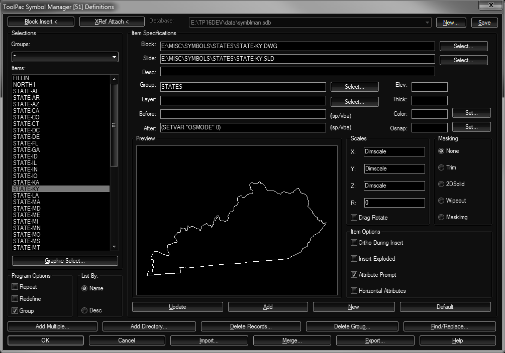
Usage Procedure:
- Select the desired symbol from the dialog. You can set the group filter to * and see a list of all symbols defined, or pull down the group selection popdown and choose a group. Upon choosing a group the list of items will be limited to only those symbols belonging to that group.
- Confirm the item chosen from the list is correct. Previewing the slide file of the symbol is one of the most important things the Symbol Manager can do to improve this process.
- Verify parameter information. If you wish to change a layer or other designation, do so now. However, scale factor overrides can be issued at the command prompt before the symbol is placed.
- Choose the Block Insert button to place a copy of the symbol into the drawing. At this prompt your options are limited to placement, scaling, and rotation. All of AutoCAD's transparent commands should work, including zoom ('Z) and pan ('P), along with snap, ortho, and osnaps, but no other command will work at this point.
Component Definitions:
Each item and group of items are explained in the sections that follow. These details can make a difference in getting maximum usage of ToolPac's Symbol Manager.
- Block Insert: When pressed, the dialog will disappear prompting you for the insertion point of the symbol. Prior to choosing this option you should have confirmed all specifications were correct. This will create a block insert in the current drawing.
- XRef Attach: When pressed, the dialog will disappear prompting you for the XRef attachment point of the symbol. This will create an external reference to the symbol in the current drawing.
- Selections:
- Groups List: When this popdown is chosen, it displays a list of all groups defined in the individual symbol definitions. You do not need to update this list, the program will update it automatically every time an individual item is added, deleted, or changed. If you choose an item from this popdown, only the symbols belonging to that group will be shown in the list below.
- Item List: This reflects the list of the symbols matching the group designation. If more items are present in the list than will fit in the window a scroll bar will appear. A single pick on an item in the list will fill in the specifications of that item and show a preview of the item.
- List By: You can choose to have the list filled with the block name or the description. If the description field is entered as records are created, this can lead to a more natural identification of items on the list. If the description method is chosen, and a particular record does not have a filled in description, the block name will be shown on the list for that record.
- Program Options: The settings in this section are not stored with each item. The status of these affect all symbols inserted.
- Repeat Mode: Turning on this toggle enables the repeat mode. When repeat mode is on, the program will continue to prompt for the placement of symbols after the dialog is closed. There will be an option on the command area to make adjustments in scale and rotation if desired. The most efficient use of this option is to preset the scales, leave the rotation angle blank and turn on the ortho toggle. You will need to press the ESC key to stop the repeat prompting for symbol placement.
- Group Mask: This toggle is used in conjunction with a 3Dface or Wipeout mask. If one of these masks is chosen, and this toggle is on, the program will bind the mask and the insert into an anonymous group. This allows the user to later easily manipulate the symbol and the mask together.
- Item Specs: The required specifications are the block name and group fields. The remaining fields are optional. The block, slide and group fields have selection buttons following the field, pressing these buttons allow you to choose from a list of choices.
- Block: The drawing file to be used, including the full drive and path. The easiest method is to use the Select button to the right of the field.
A special option exists for users who wish to use a Symbol Manager group simply to launch lisp or vba routines. For the Block name enter "NOINSERT" (without the quotes), Symbol Manager won't attempt to insert a block.
- Slide: The slide file representing the drawing. This field is usually filled in automatically upon designation of the drawing.
- Desc: A description for the symbol.
- Group: The group the symbol belongs to. The use of group names allows you to isolate the list (and graphic select) to only those symbols in the group, speeding up the process of finding the right symbol. A selection button to the right allows you to quickly choose from existing group names used.
- Layer: The layer to insert the symbol on. Leaving the field blank inserts it on AutoCAD's current layer. A selection button to the right allows you to quickly choose from existing layer names.
- Before: A statement of LSP or VBA code to be executed 'before' the symbol is inserted.
- After: Same as above, but executes 'after' the symbol is inserted.
- Elev: An optional elevation to use for inserting the symbol.
- Thick: An optional thickness to use for inserting the symbol.
- Color: An optional color to use for inserting the symbol. It is a number in the range from 0 to 256. Number 0 can be used to indicate BYBLOCK and 256 to indicate BYLAYER. A selection button to the right allows you to quickly choose from the AutoCAD color palette.
- Osnap: An optional integer that is the sum of the numbers for desired toggles. A selection button to the right allows you to quickly set the toggles.
- Block: The drawing file to be used, including the full drive and path. The easiest method is to use the Select button to the right of the field.
- Scales: Fields to control the default values of xyz scales, as well as the rotation of the symbol. These values can be overridden at the prompt area after the insert is initialized.
The value "Dimscale" is the default. This allows you to insert symbols at the dimension scale which can vary between drawings. To check or set this value, enter DIMSCALE at the command prompt. This value also exhibits special behavior if DIMSCALE=0. If the dimscale is zero, and you are inserting in paper space viewports, the scale factor is calculated as the scale of the current viewport. In this same situation, if the symbol is inserted in paper space, the value reverts to 1.0.
You may also use the user variables USERR1 through USERR5, simply put these words in as the scale factor.
A popular method of controlling rotation is to leave the rotation angle field blank, and possibly turning on the ortho toggle in the options section (explained below). This allows you to drag the rotation angle of the symbol after specifying the insertion point. There is a toggle provided to aid in this setting.
- Masking: This provides an option for the 'bounding box' of the symbol to be masked or trimmed. The bounding box is a rectangular area bounding the symbol and any included attributes. Each option explained in detail below.
- None: No masking or trimming is done.
- Trim: All 'trimmable' geometry inside the bounding box is erased. All geometry completely inside the bounding box is erased.
- 2DSolid: Creates a 2DSolid with the color 254 behind the inserted symbol. On most plotters this produces a white masking effect.
- Wipeout: Some installations of AutoCAD include support for the wipeout object. Symbol Manager checks for the existence of this support and will gray-out this radio button if the support is not present.
- MaskImg: Masks the area using an image bitmap. This achieves the same results as the Wipeout explained above.
- To control the visibility of the masking object frame, use AutoCAD's IMAGEFRAME command.
- This option utilizes AutoCAD's image system, which does not store images inside the drawing, but rather references them as external files. As such the small image used in this option is also stored externally. While you may not distribute any other part of the software application, you are hereby given the right to include the file WIPEOUT.BMP with your drawings if given to others. If you give someone the drawing without the BMP, they will not receive an error message, but the mask will not appear.
- Item Options: These are options affecting each symbol. These settings are stored with the symbol data and can vary with each definition.
- Ortho During Insert: Turning on this toggle will turn on AutoCAD's ortho mode during the duration of the symbol insert.
- Insert Exploded: Turning on this toggle causes the symbol geometry to be inserted already exploded into its component parts.
- Attribute Prompt: Determines where the routine should pause for entry of attributes if they exist in the block definition. Symbol Manager always uses the dialog based version of attribute entry and will not provide the entry at the command prompt.
- Horizontal Attributes: Turning on this toggle causes all attributes in the insert to be rotated back to horizontal regardless of the rotation angle of the symbol. This usually works best with short (1-3 character) values defined with a 'middle' justification.
- Item Control: These buttons control aspects of the currently displayed symbol.
- Update: This button is used to immediately update the item record with the specifications you have entered. The program updates records on item change, so this is usually not necessary.
- Add: This button is used to add a new symbol to the list after all parameters have been set. You should choose the new button before filling in the specifications.
- New: This button is used to clear all item specifications before adding another symbol to the list.
- Default: Use this button when the various item properties fields are set to what would be desired as default values. These values are stored:
XScale Layer Explode Osnap Value YScale Color Attr Prompt Ortho Option ZScale Elevation Run Before Mask Option Rotation Thickness Run After Attr Horz
- Delete: These buttons control the database of symbol definitions.
- Add Multiple: Allows you to add multiple symbols at one time, see section below.
- Add Directory: Allows you to add all symbols in a directory, see section below.
- Delete Records: Presents a list box of all symbols in the currently selected group, and allows you to select any or all selected items from that list. In the event of accidental removal of definitions, choose the cancel button at the main dialog to discard changes.
- Delete Group: Presents a list box of groups in the database. Select the group you wish to delete and click OK. Once the dialog is closed and changes saved, the group will no longer exist.
- Find/Replace: Make multiple changes to the currently selected group. See section below.
- Program Control: These buttons (on the bottom row) control the application.
- OK: This closes the Symbol Manager dialog and stores any changes to the definition database.
- Cancel: This closes the Symbol Manager dialog and discards any changes to the definition database.
- Import: This button is used to import a list of comma separated values from a file. Warning, the import option replaces the entire list with those values in the import file.
- Merge: This button is used to merge a list of comma separated values from a file. The merged data is appended to the list and the group and item lists are updated automatically. This can be used to merge groups of similar symbols.
- Export: This button is used to export a list of comma separated values to a file. Only the selected groups will be exported to the file. These files can be later imported or merged and can be easily edited with any spreadsheet program.
Note on version differences. This version of the Symbol Manager will import data exported from any previous version. However the reverse is not true. If you intend to provide an export for a user of a previous version, the export file will need to be opened in Excel, then the last 6 columns should be deleted.
Graphics Select:
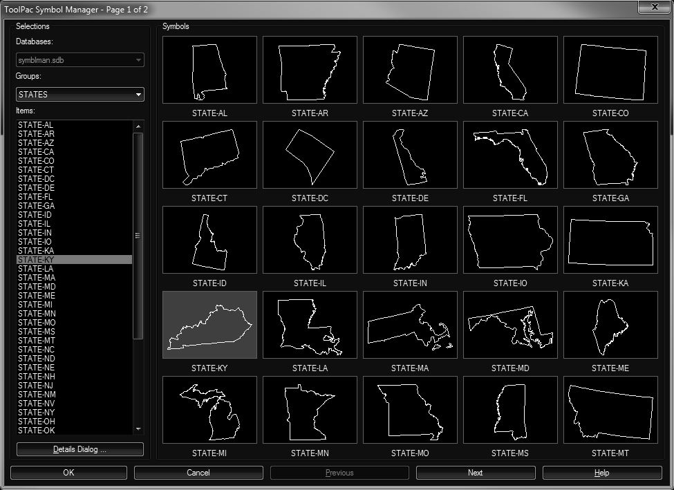
It is often difficult to determine the proper symbol by its name. In these cases you can use the Graphic Select to choose the desired symbol. The dialog below will appear, showing the first 25 symbols in the current list. If a group has been chosen, the only symbols that will appear in the dialog are the ones belonging to that group. To view all symbols graphically, simply set the group name to * in the main dialog.
Once the first page of symbols are shown, if there are more than 25 items in the current group the Next button will be available to page to additional symbols. If the Next or Previous buttons are grayed out, it means there are no more symbols in that direction. The caption bar will show the current page number as well as the maximum number of pages.
Single clicking on the desired symbol in the array will exit this dialog and begin the insertion process at the command prompt area. If you select a symbol by its name on the list at left, it will highlight on the graphic tile array. Pressing the OK button with a symbol selected in this manner will also begin the insertion process.
At any time you may choose the 'Details Dialog' button to return to that control panel.
Adding Multiple Files:
A more efficient way of adding multiple selective symbols to the definition list is to use the Add Multiple button. If you wish to add an entire directory of symbols, see the section below. You will first be presented with the following dialog.
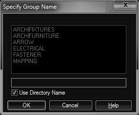
This is used to designate the group name for the multiple symbols to be added. The default is to use the last element of the directory name as the group name. As an example, F:\SYMBOLS\ELECTRICAL becomes a group name ELECTRICAL. To use an existing group name, remove the check box from the 'Use Directory Name' toggle, and choose the desired group name from the list. To use a new group name, remove the check box from the 'Use Directory Name' toggle, and type in the desired name in the edit field.
You will be presented with the multi-file selection dialog. Select the drawings you wish to add to the list. The dialog title area will display the progress of the operation. In the process of selecting symbols, you do not need to be concerned whether a symbol is already defined. Symbol Manager will not allow duplicate items within a single group. So if in doubt, choose the symbol again. Keep in mind that you can have the same symbol name in a different group.
It would be a good idea to use ToolPac's Make Symbol Slides in the multiple mode to process all of your slides before executing this operation.
Adding Multiple Files:
Since many factors involved in adding a directory of symbols behave exactly like the add multiple, it is recommended that you read that section above. The Add Directory method is the most efficient way of adding all symbols in a particular directory.
You will be presented with ToolPac's directory select dialog. Once a directory is chosen, all drawings in that directory will be added to the definitions under the group name specified.
As in add multiple, it would be a good idea to use ToolPac's Make Symbol Slides in the directory mode to process all of your slides before executing this operation.
Find & Replace:
The Find & Replace option can save many hours of repetitious revisions when you need to make a change to many definitions. One classic case is when the symbols must be moved to another drive and/or directory. Another example would be group renaming.
Only the fields that are checked are affected by this operation. Also, this operation only affects those definitions in the current list. So if a group name has been chosen, only those items in the group are affected. To process all definitions, choose * at the group pulldown. Changes are not committed to the database file until you OK out of the main dialog box. So if you make a mistake in this process, simply Cancel at the main dialog and execute the process again.
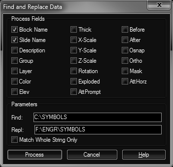
The method for the directory change example is shown in the dialog above. Note that the path is stored in the slide name field and should be selected as well.
Certain fields are on/off or multiple choice numbers, some have ranges. Use the table below to determine appropriate values for these fields.
- Color: A number in the range from 0 to 256. Number 0 can be used to indicate BYBLOCK and 256 to indicate BYLAYER. Note that leaving the field empty is often best, applying no color changes to the insert.
- Rotation: A number in the range from 0 to 359 indicating the rotation angle in degrees. This field can be set to blank to allow prompting during insert. Simply put nothing in the replace field to blank out the rotation field.
- Exploded: A toggle field, use 0 for off, 1 for on.
- Osnap: An integer that is the sum of the numbers for desired toggles.
- NONe
- ENDpoint
- MIDpoint
- CENter
- NODe
- QUAdrant
- INTersection
- INSertion
- PERpendicular
- TANgent
- NEArest
- QUIck
- Ortho: A toggle field, use 0 for off, 1 for on.
- Mask: A number from 1 to 5.
- None
- Trim
- 2DSolid
- Wipeout
- MaskImg
- AttHorz: A toggle field, use 0 for off, 1 for on.
Multiple Databases:
In the event that you have an enormous amount of symbols that do not lend themselves to being managed in a single symbol database, you can implement multiple symbol databases. The definitions for a single database in Symbol Manager are stored in a file called SYMBLMAN.SDB. By default you will have only one of these files, and it will reside in the application folder. The application will automatically create this file on first execution and will update it thereafter.
In the upper right corner of the Symbol Manager dialog is a popdown to select the 'current' database. If you have not created multiple databases there will only be one listed and the popdown will be disabled. However, if you create multiple databases (*.sdb files) on your system (and add those folders to your support paths) there will be multiple databases to choose from. Selecting a new database switches the working database and the contents of the Symbol Manager changes. Symbol Manager databases may have any name, and use the file extension ".sdb".
To create a new database, choose the button in the upper right corner of the Symbol Manager details dialog. For the *.sdb file created to be found when Symbol Manager starts up, this file must reside in a folder that is in the AutoCAD support file search paths.
If the SDB file is flagged as read-only by the operating system (you can control this with Windows Explorer) the program will gray out all the edit fields and update related buttons.
Menu Calls:
Users may wish to set Symbol Manager initial variables in their menus or custom lisp to control the initial database, group, and dialog displayed. For example a menu may look like this:
| Symbols |
|---|
| Architectural ... |
| Appliance ... |
| Ceiling ... |
| Door .... |
In the menu coding, the customizing user would have the ability to add a call to the variable setting routine.
(dstp_symblset dbf grp dia)
Where:
- dbf - The initial database file to use. As this is a LISP string, path separators must be double backslashes "\\", such as
D:\\PATH\\ELECTRICAL.SDBif called from a user lisp. However, in menu code the \\ is interpreted as a pause, and a single forward slash "/" must be used . - grp - The initial group name as a string, which must be enclosed in quotes. This group name should be used at least once in the database designated. The group name should be entered as upper case.
- dia - The initial dialog displayed. Specify a value of 1 for the details panel, and 2 for the graphic select panel.
Note: If you do not want to specify one of these parameters, use nil for the value. Such as:
(dstp_symblset "D:\\PATH\\MYDATA.SDB" nil 1)
This same example with an initial group and the graphic select dialog would be:
(dstp_symblset "D:\\PATH\\MYDATA.SDB" "MYGROUP" 2)
[Arch ]^c^c(dstp_symblset "D:/PATH/ARC.SDB" "DOOR_WINDOW" 2) (dstp_symblman)
Note: The presence of the final space in the example above.
Slide Libraries:
When folders of symbols are frequently appended or changed, it's often best to leave the individual slides for these folders. However when a folder is considered complete, you may want to consider rolling up all the SLD files in that folder into a single SLB. DotSoft's SlideMan 2.0 or the AutoCAD provided SLIDELIB.EXE can be used to accomplish this. To allow the Symbol Manager to see the slides once they are moved into the SLB, a quick Find & Replace operation is necessary.
Take for example, that you had numerous slides in a folder named D:\SYMBOLS\ELECTRICAL with filenames like D:\SYMBOLS\ELECTRICAL\AA171.SLD, D:\SYMBOLS\ELECTRICAL\AA172.SLD, etc. These references in the slide field of Symbol Manager would need to be changed to D:\SYMBOLS\ELECTRICAL\ELECTRICAL(AA171), D:\SYMBOLS\ELECTRICAL\ELECTRICAL(AA172), etc.
Procedure:
- Select the appropriate group for processing. For data integrity, this must coincide with the same group of files moved into the slide library (SLB).
- Choose the Find & Replace button.
- Turn on the Slide File toggle.
- In the Find field, enter the drive & path including the final backslash such as
D:\SYMBOLS\ELECTRICAL\. - In the Replace field, enter the drive, path, and name of the slide library, followed by an opening/left parenthesis, such as
D:\SYMBOLS\ELECTRICAL\ELECTRICAL(. - Repeat steps 1 through 5, this time entering ".SLD" for the Find field, and a closing/right parenthesis ")" for the Replace field.
Masking Buffer:
The default value for the masking buffer is not defined by default, resulting in no additional space around symbols as they are masked. If you would like additional space around symbols you can change the value of the masking buffer. At the command line enter SYMBLBUF and put in a new value ranging from 0.0 to 100.0.
Note: If you are running the full ToolPac, this command is not defined until Symbol Manager has been executed. ToolPac demand loads modules.
Symbol Slides:
This tool is used to prepare symbol slides for Symbol Manager. Slides have a distinct advantage over the drawing preview bitmap. The bitmap is typically limited to 180x140 pixels, which cannot compare to the vector detail stored in the slide file. The preview bitmap cannot be scaled up without looking extremely jagged. The vector representation in our main preview window is roughly four times larger and remains crisp.
This slide preparation routine needs to be run while there is no drawing active. Begin a new empty drawing before beginning the procedure. Once the tool is chosen, the following dialog appears.
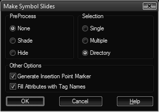
- Preprocess: The slide file that AutoCAD creates can be affected by commands that are executed beforehand. This section allows you to choose to execute the SHADE or HIDE commands before the slide is created.
- Selection: Designate how you would like to proceed in processing the slides.
- Single: Presents a dialog allowing you to select a single drawing file, then creates a slide of that file.
- Multiple: Presents a multi-select dialog allowing you to choose several files in one folder for processing.
- Directory: Presents a select folder dialog, then proceeds to process all drawings in that folder.
- Insertion Marker: This option places a red asterisk marker at the insertion point of the symbol before creating the slide. This can be very handy during symbol placement. This does not affect the geometry of the drawing symbol, only the appearance of the slide.
 Block Symbol Manager